
Operation Manual

• 3 or 4 point blade (Fig. 4)
WARNING!
Wear protective gloves
and t the blade guard.
– Remove the blade (if tted) as described in
paragraph 4.
– The guard (1) is xed to the angle transmission
(2) by four screws (3).
• Cutting line head (Fig. 5)
WARNING!
When using the cutting
line head the additional guard, with line cut-
ting knife, must always be tted.
– Remove the blade (if tted) as described in
paragraph 4.
– The guard (1) is xed to the angle transmission
(2) by four screws (3).
– Assemble the additional guard (4) fastening it
into place on the guard (1).
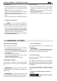
4. REMOVING AND REFITTING
THE CUTTING DEVICES
WARNING!
Use only original cutting
devices or ones homologated by the Ma nu-
facturer.
• 3 or 4 point blade (Fig. 6)
WARNING!
Wear protective gloves
and t the blade guard.
NOTE
The fastening nut (5) has a
left-hand thread and so must be unscrewed in a
clockwise direction and screwed up anticlockwise.
– Insert the wrench supplied (2) into the specic
hole in the angle transmission (3) and rotate the
blade (1) by hand until the wrench enters the
inner hole, blocking rotation.
– Remove the split pin (4) and unscrew the nut (5)
in a clockwise direction.
– Pull out the washer (6) and the outer ring-nut (7)
and remove the blade (1).
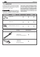
IMPORTANT
The machine is supplied with
some of the components disassembled and the
fuel tank empty.
WARNING!
Always wear strong work
gloves to handle the cutting devices. Mount
the components very carefully so as not to
impair the safety and eciency of the ma
chine. If in doubt, contact your dealer.
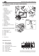
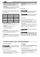
1. COMPLETING THE MACHINE
1a. “MONO” models (Fig. 1)
– Position the upper part (2) with the front grip’s
guard on the drive tube (1).
– Fasten the lower cap (4) inserting the pin (4a) in
one of the three holes on the drive tube.
– Fully tighten the screws (4).
1b. “DUPLEX” models (Fig. 2)
– Loosen the screws (5) and remove the cap (4)
from the support (2).
– Put the handlebar (1) into the seating in the sup-
port (2), located on the drive tube (3), making
sure that the controls are on the right.
– Fit the cap (4), fully tightening the screws (5).
– Fasten the casing (6) of the controls to its cable
fastener (7).
2. MOUNTING THE ROD
(Models with separate rod – Fig. 3)
– Pull out the stop pin (5) and push the lower part
of the rod (4) right down until the stop pin (5)
slots into the hole (6) in the rod. This is easier to
do if you rotate the bottom of the rod (4) slightly
in both directions. The pin (5) is in place when it
is completely lodged in the hole.
– Lastly, tighten the knob (7) securely.
3. FITTING THE GUARDS
WARNING!
Each cutting device is pro-
vided with a specic guard. Never use guards
other than those indicated for each cutting
device.
106 MACHINE ASSEMBLY
EN
4. MACHINE ASSEMBLY