Hydro Shark Electric Boiler (07-36 KW) Installation Manual and Owner’s Guide 12-36 KW UL 834 07-10 KW UL 499 The Hydro Shark Electric Boiler features advanced technology, impressive energy-saving performance, and a compact design. Exclusively manufactured by Stiebel Eltron, a leader in heating technologies for the past 80 years. • • • • • • • Featuring Efficiency: 100 % Wall Hung Flow Activated: .
CONTENTS Installation Manual SPECIFICATIONS..........................................................................................................4 INTRODUCTION............................................................................................................5 MOUNTING THE UNIT...................................................................................................6 INSTALLATION.............................................................................................................
Installation Manual CONGRATULATIONS Congratulations and thank you for choosing our micro boiler. Before use, we recommend that you read through this installation manual carefully. Keep this manual for future reference. If you need an additional manual, contact the manufacturer or your local distributor. When you call, please tell us the product name and the serial number of your unit written on the rating plate of the boiler.
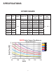
SPECIFICATIONS HYDRO SHARK VOLTS WIRE SIZE AMP DRAW (MAX) DBL POLE BREAKER SIZE BTU MODEL KW SH-07 7 8 30 (1) 40 24,573 SH-10 10 6 40 (1) 50 32,765 SH-12 12 4 50 (1) 70 40,956 SH-14 14 2x8 60 (2) 40 49,147 SH-19 19 2x6 80 (2) 50 65,526 SH-24 24 2x4 100 (2) 70 81,912 SH-29 29 3x6 120 (3) 50 98,977 SH-36 36 3x4 150 (3) 70 122,868 240 WATER TEMP RANGE 86° - 140° F Boiler Flow-GPM SH-XX Boiler Temp vs Flow Rate with 70 Deg F Return Fluid 8 7 6 ____ __
INTRODUCTION IMPORTANT! Read this entire manual. Failure to follow all the guides, instructions and rules could cause personal injury or property damage. Improper installation, adjustment, alteration, service and use of this unit can result in serious injury. This unit must be installed by a licensed electrician and plumber. The installation must comply with all national, state and local plumbing and electric codes. Proper installation is the responsibility of the installer.
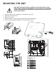
MOUNTING THE UNIT UNIT MUST BE INSTALLED IN A VERTICAL POSITION WITH THE WATER FITTINGS POINTING DOWNWARD. DO NOT INSTALL UNIT WHERE IT WOULD ROUTINELY BE SPLASHED WITH WATER OR ELECTRICAL SHOCK MAY RESULT. 1. 2. 3. 4. 5. Leave a minimum of 5” clearance on all sides for servicing. Make sure the power is off. Remove the cover. Mount securely to wall by putting screws through mounting holes. Screws and plastic wall anchors for mounting are provided.
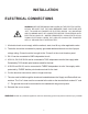
INSTALLATION ELECTRICAL CONNECTIONS WARNING: BEFORE BEGINNING ANY WORK ON THE ELECTRIC INSTALLATION, BE SURE THAT THE MAIN BREAKER PANEL SWITCHES ARE “OFF” TO AVOID ANY DANGER OF ELECTRIC SHOCK. ALL MOUNTING AND PLUMBING MUST BE COMPLETED BEFORE PROCEEDING WITH ELECTRICAL HOOK-UP. WHERE REQUIRED BY LOCAL,STATE OR NATIONAL ELECTRICAL CODES THE CIRCUITS SHOULD BE EQUIPPED WITH A “ GROUND FAULT INTERRUPTER”. 1. All electrical work must comply with the national, state, local & any other applicable codes. 2.
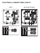
ELECTRICAL CONNECTIONS CONT’D SH-14, SH-19, SH-24 CKT 1 CKT 2 8 OF F ON OF F ON ON ON ON OF F OF F OF F OF F CKT 1 ON SH-12
ELECTRICAL CONNECTIONS CONT’D SH-29, SH-36 ON ON ON ON ON ON OF F OF F OF F OF F OF F OF F CKT 1 CKT 2 CKT 3 CIRCUIT CONNECTION Please refer to specification table for wiring and circuit breaker size. See technical data section for wiring diagrams.
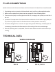
FLUID CONNECTIONS NOTE: EXCESSIVE HEAT FROM SOLDERING COPPER PIPES NEAR THE BOILER MAY CAUSE DAMAGE. 1. All plumbing work must comply with the national, state, local & any other applicable codes. 2. Make sure the radiant floor system has been purged & is free of floating debris. 3. The return side (inlet) is on the right side of the unit, the supply side (outlet) is on the left of the unit. 4. A pressure & temperature relief valve should be installed on the hot water supply side (outlet) of the unit.
WIRING DIAGRAMS 4 2 6 4 2 5 3 1 5 3 1 CKT 1 CKT 2 4 2 4 2 4 2 5 1 5 1 5 1 6 4 5 4 CKT 3 2 7/8 3 2 7/8 5 3 1 SH-24 1 14 15 13 SH-24 1 4 2 6 4 2 6 4 2 5 3 1 5 3 1 5 3 1 5 14 15 SH-29 12 4 6 2 9/10 2 3 4 5 4 6 9/10 13 CKT 2 11/12 11/12 1 CKT 1 6 CKT 1 CKT 2 356 CKT 3 6 11/12 4 5 4 6 9/10 2 3 2 7/8 13 1 14 15 3 5 SH-36 1 > SH-36 Note: 1. Boilers are considered a continuous load. 2. Copper conductors only.
APPLICATIONS • • WARNING • Space Heating Applications In order to purge air in water pipes within a closed loop system, an air vent, air separator, and expansion tank should be installed in the system. (Hydro Smart pre-built space heating panels incorporate all of these features). Water temperature over 125° F (52° C) can cause sever burns instantly of death from scalding. Chemicals such as diluted Glycol can be used for radiant floor, Hydro/fan coil air or Baseboard heating only.
Dual-purpose hot water heating (Domestic and Space Heating) Insert a Hydro Smart Combi Panel to provide potable heated water and Hydronic Heating (with space heating panel(s)) with one heat source. The Hydro Smart Combi Panel integrates with a wide variety of boilers and delivers “Priority” potable heated water with no storage tank and hydronic space heating in a small reliable package.
Owner’s Guide CONGRATULATIONS Congratulations and thank you for choosing our micro boiler. Before use, we recommend that you read through this owner’s guide carefully. Keep this manual for future reference. If you need an additional manual, contact the manufacturer or your local distributor. When you call, please tell us the product name and the serial number of your unit written on the rating plate of the boiler.
TROUBLESHOOTING General Symptom Possible Cause Solution No Hot Water •No Power •Safety Thermal Cut Off Tripped •Not Enough Flow Rate To Activate •Plugged Flow Sensor •Utility Controlling Load •Reset Thermal Cut Off •Wrong Size Pump •Activate Thermostat/ Clean Flow Sensor Water Not Hot Enough •Water Flow Too High •Voltage To Low •Glycol/Water Ratio Too High •Manifold or Ball Valve Closed •Reduce Water Flow Rate •Supply Correct Voltage to Unit •More than 20%, less than 50% •Open Loops/Ball Valves LE
COMPONENTS DIAGRAM A C I B A- Fluid Temp.
PARTS LIST Part Number Description 286356 Housing, SH-12 thru SH-36 245307 Temperature Control Knob, SH-07 thru SH-36 279998 Wiring Block, SH-07- thru SH-12 279997 Wiring Block, SH-14- thru SH-24 279996 Wiring Block, SH-29- thru SH-36 286360 Heating System, SH-12 286361 Heating System, SH-14 286362 Heating System, SH-19 286364 Heating System, SH-24 286373 Heating System, SH-29 286374 Heating System, SH-36 286369 High Limit, SH-07 thru SH-36 286366 Electronic Control Device Board,
Boiler Pressure Drops Table (Boilers SH-12 thru SH-36) This table is used for sizing Primary (Boiler) Circulator All boilers must use Primary/Secondary circuitry. This is used to create Hydraulic seperation between the Boiler and Emitter circulators allowing you to create 30 57.5 25 46 20 34.5 15 23 10 11.5 5 0 0 Flow Pressure (HD Feet) Flow Pressure (PSI) 69 SH-29,36 SH-7,10 SH-14,19,24 SH-12 0 .5 1 1.5 2 2.5 3 FLOW GPM 18 3.5 4 4.
NOTES: 19