
Manual


22 | SB S | SB AC WWW.STIEBEL-ELTRON.COM
INSTALLATION
SPECIFICATION
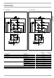
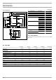
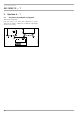
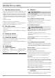
15.1.5 SB 650/3 AC
1305
965
450
1850
1725
1480
1135
560
125
125
750
690
50
950
c01
d33
c10
d34
c06
i02
i03
i04
i18
D0000017587
SB 650/3 AC
c01 Cold water inlet Male thread G 1 1/2 A
c06 DHW outlet Male thread G 2 A
c10 DHW circulation Male thread G 1/2
d33 Heat source flow Male thread G 3/4 A
d34 Heat source return Male thread G 3/4 A
h43 Thermometer Male thread G 1/2 A
i02 FlangeI
Diameter mm 280
Pitch circle diameter mm 245
Screws 12 x M14
Torque Nm 85
i03 FlangeII
Diameter mm 280
Pitch circle diameter mm 245
Screws 12 x M14
Torque Nm 85
i04 Flange III
Diameter mm 280
Pitch circle diameter mm 245
Screws 12 x M14
Torque Nm 85
i07 Electric emergency/booster
heater
Female thread G 1 1/2
i18 Protective anode
15.2 Fault conditions
In the event of a fault, temperatures of up to 95°C at 0.6MPa
can occur.
15.3 Data table
SB 302 S SB 402 S SB 602 AC SB 1002 AC SB 650/3 AC
185354 185355 071554 071282 003039
Hydraulic data
Nominal capacity l 300 400 600 1000 650
Application limits
Max. permissible temperature °C 110 110 110 110 110
Max. permissible pressure MPa 1.0 1.0 1.0 1.0 1.0
Test pressure MPa 1.5 1.5 1.5 1.5 1.5
Max. flow rate l/min 38 45 50 70 50
Versions
Sealed unvented type
Dimensions
Height mm 1585 1755 1685 2525 1725
Width mm 700 750 750 750 750
Depth mm 700 750 800 800 830
Weight
Weight (full) kg 401 519 754 1212 840
Weight (empty) kg 101 119 154 212 190