Bedienung und Installation Operation and installation Utilisation et installation Bediening en installatie Эксплуатация и монтаж Geschlossener Warmwasser-Kombi-Standspeicher | Sealed unvented floorstanding DHW combi cylinder | Ballon mixte sur pieds pour eau chaude sanitaire en circuit fermé | Gesloten staande warmwater-combiboiler | Закрытый напольный комбинированный водонагреватель »» »» »» »» »» SB SB SB SB SB 302 S 402 S 602 AC 1002 AC 650/3 AC
Inhalt | Bedienung Allgemeine Hinweise Bedienung ��������������������������������������������� 2 1. Allgemeine Hinweise �������������������������������������������2 1.1 1.2 2. 2.1 2.2 3. 4.
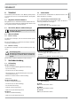
2. Sicherheit 4. 2.1 Bestimmungsgemäße Verwendung »» Lassen Sie die das Gerät, die Sicherheitsgruppe und das einge- Das Gerät ist ein universell zu verwendendes Druckgerät zur Warmwasserversorgung. Geeignete Blindflansche, Wärmeaustauscher und Elektro-Heizflansche können vom Fachhandwerker eingebaut werden. Das Gerät ist für den Einsatz im häuslichen Umfeld vorgesehen. Es kann von nicht eingewiesenen Personen sicher bedient werden. In nicht häuslicher Umgebung, z. B.
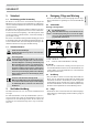
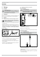
Bedienung Was tun wenn ... 5. Was tun wenn ... 5.1 ... Störungen am Gerät auftreten Rufen Sie den Fachhandwerker. Zur besseren und schnelleren Hilfe teilen Sie ihm die Nummer vom Typenschild mit (000000-0000-000000): SB 602 AC 600 l St em Nr.: 000000 - 0000 - 000000 1 MPa (10 bar) 50 l/min Made in Germany 4 | SB S | SB AC 26_02_09_0034 max. 110°C www.stiebel-eltron.
6. Sicherheit Die Installation, Inbetriebnahme sowie Wartung und Reparatur des Gerätes darf nur von einem Fachhandwerker durchgeführt werden. 6.1 Allgemeine Sicherheitshinweise Wir gewährleisten eine einwandfreie Funktion und Betriebssicherheit nur, wenn das für das Gerät bestimmte Original-Zubehör und die originalen Ersatzteile verwendet werden. 6.2 7.2 Sonderzubehör Als Sonderzubehör sind Blindflansche, Wärmeaustauscher und Elektro-Heizflansche erhältlich. 7.2.
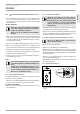
Installation Montage 8. Montage 8.3.2 Signalanode kontrollieren / montieren 8.1 Transport SB 302 S und SB 402 S SB 302 S und SB 402 S Für den Transport zum Aufstellort empfehlen wir die Speicherverkleidung zu demontieren, damit diese nicht beschmutzt oder beschädigt wird. ! 8.2 ! Beschädigungsgefahr! Das Gerät darf nicht ohne oder mit beschädigter Verbrauchsanzeige betrieben werden, da sonst nach Abnutzung der Anode Wasser austritt.
Installation Montage 8.3.5 Sonderzubehör montieren SB AC: Die Styroporkappe in der unteren Flanschöffnung dient auch zur korrekten Positionierung der Wärmedämmung über den Flanschöffnungen. Wenn Sie Sonderzubehör in der unteren Flanschöffnung einbauen, stecken Sie die Styroporkappe in die obere Flanschöffnung. »» Eine Zirkulationsleitung montieren Sie am Zirkulationsanschluss, Sie können gegebenenfalls auch den Anschluss des Thermometers nutzen (siehe Kapitel „Technische Daten / Maße und Anschlüsse“).
Installation Erstinbetriebnahme 9. 14. Wartung Erstinbetriebnahme »» Öffnen Sie ein nachgeschaltetes Zapfventil so lange, bis das Gerät gefüllt und das Leitungsnetz luftfrei ist. Sie die Durchflussmenge ein. Beachten Sie dabei, die maximal zulässige Durchflussmenge bei voll geöffneter Armatur (siehe Kapitel „Technische Daten / Datentabelle“). Reduzieren Sie gegebenenfalls die Durchflussmenge an der Drossel der Sicherheitsgruppe.
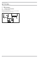
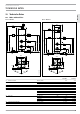
Installation Technische Daten deutsch 15. Technische Daten 15.1 Maße und Anschlüsse 15.1.1 SB 302 S 15.1.2 SB 402 S i18 750 600 c06 i18 c06 h43 i07 h43 i07 1145 1160 725 1025 710 1160 75 c03 i02 55 c01 i03 360 55 75 i02 1040 1040 i03 1755 1585 c10 375 c10 c01 c03 700 550 c01 c03 Kaltwasser Zulauf Kaltwasser Zulaufrohr c06 c10 h43 i02 Warmwasser Auslauf Zirkulation Thermometer Flansch I i03 Flansch II i07 i18 elektr. Not-/Zusatzheizung Schutzanode www.
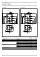
Installation Technische Daten 15.1.3 SB 602 AC 15.1.4 SB 1002 AC i18 i18 c06 c06 c10 h43 2640 2525 i02 880 115 c01 530 530 115 880 i02 i03 1790 1685 1200 1150 i03 1200 h43 i07 1840 1800 i07 1200 c10 c01 950 750 750 50 50 690 690 950 45° 45° 45° c01 c06 c10 h43 i02 Kaltwasser Zulauf Warmwasser Auslauf Zirkulation Thermometer Flansch I i03 Flansch II i07 i18 elektr.
15.1.5 SB 650/3 AC c01 c06 c10 d33 d34 h43 i02 i18 c06 i04 125 125 450 1850 1480 1135 d33 i02 i03 560 965 1305 i03 1725 c10 i04 c01 d34 50 950 Außengewinde Außengewinde Außengewinde Außengewinde Außengewinde Außengewinde Durchmesser Lochkreisdurchmesser Schrauben Anzugsdrehmoment Flansch II Durchmesser Lochkreisdurchmesser Schrauben Anzugsdrehmoment Flansch III Durchmesser Lochkreisdurchmesser Schrauben Anzugsdrehmoment elektr.
Germany Kundendienst und Garantie Erreichbarkeit Sollte einmal eine Störung an einem unserer Produkte auftreten, stehen wir Ihnen natürlich mit Rat und Tat zur Seite. Soweit eine Garantieleistung erbracht wird, übernehmen wir keine Haftung für die Beschädigung eines Gerätes durch Diebstahl, Feuer, Aufruhr oder ähnliche Ursachen.
Germany Umwelt und Recycling deutsch Entsorgung von Transport- und Verkaufsverpackungsmaterial Damit Ihr Gerät unbeschädigt bei Ihnen ankommt, haben wir es sorgfältig verpackt. Bitte helfen Sie, die Umwelt zu schützen, und entsorgen Sie das Verpackungsmaterial des Gerätes sachgerecht. Wir beteiligen uns gemeinsam mit dem Großhandel und dem Fachhandwerk / Fachhandel in Deutschland an einem wirksamen Rücknahme- und Entsorgungskonzept für die umweltschonende Aufarbeitung der Verpackungen.
Contents | Operation General information Operation �������������������������������������������� 14 1. General information ������������������������������������������ 14 1.1 1.2 2. 2.1 2.2 3. 4.
Operation Safety 2. Safety 4.1 2.1 Intended use Appliance versions with signal anode Risk of damage If the consumption display changes colour from white to red, have the protective anode checked by a heating contractor and if necessary replaced. ! This appliance is designed for domestic use. It can be used safely by untrained persons. The appliance can also be used in a nondomestic environment, e.g. in a small business, as long as it is used in the same way.
Installation Safety 6. Safety 7.2 Special accessories Only qualified contractors should carry out installation, commissioning, maintenance and repair of the appliance. Dummy flanges, indirect coils and flanged immersion heaters are available as special accessories. 6.1 7.2.1 General safety instructions We guarantee trouble-free operation and operational reliability only if the original accessories and spare parts intended for the appliance are used. 6.
8. Installation 8.3.2 Checking/fitting the signal anode 8.1 Transport SB 302 S and SB 402 S SB 302 S and SB 402 S To prevent damage and soiling, we recommend removing the cylinder casing for transportation to the installation location. ! 8.2 Risk of damage The appliance must not be operated without a consumption indicator or with a damaged one, otherwise water will leak out once the anode is depleted.
Installation Installation 8.3.3 Preparing the DHW circulation line connection, if applicable 8.3.5 Fitting special accessories SB AC: The polystyrene cap in the lower flange aperture is also designed to position the thermal insulation correctly above the flange apertures. If you fit the special accessories into the lower flange aperture, then push the polystyrene cap into the upper flange aperture.
Installation Commissioning 14. Maintenance Commissioning »» Open a downstream draw-off valve until the appliance has filled Danger of electrocution! Before any work on the appliance, disconnect all poles from the power supply. up and the pipes are free of air. »» Adjust the flow rate. For this observe the maximum permissible flow rate with a fully opened tap (see chapter "Specification / Data table"). If necessary reduce the flow rate at the butterfly valve of the safety assembly. »» Carry 14.
Installation Specification 15. Specification 15.1 Dimensions and connections 15.1.1 SB 302 S 15.1.
Installation Specification 15.1.3 SB 602 AC 15.1.4 SB 1002 AC c06 c06 c10 h43 2640 2525 i02 880 c01 530 115 530 115 880 i02 i03 1790 1685 1200 1150 i03 1200 h43 i07 1840 1800 i07 1200 c10 ENGLISH i18 i18 c01 950 750 750 50 50 690 690 950 45° 45° 45° c01 c06 c10 h43 i02 Cold water inlet DHW outlet DHW circulation Thermometer Flange I i03 Flange II i07 i18 Electric emergency/booster heater Protective anode www.stiebel-eltron.
Installation Specification 15.1.
Warranty | Environment and recycling Warranty The warranty conditions of our German companies do not apply to appliances acquired outside of Germany. In countries where our subsidiaries sell our products, it is increasingly the case that warranties can only be issued by those subsidiaries. Such warranties are only granted if the subsidiary has issued its own terms of warranty. No other warranty will be granted.
Table des matières | Utilisation Remarques générales Utilisation ������������������������������������������� 24 1. Remarques générales ���������������������������������������� 24 1.1 1.2 2. 2.1 2.2 3. 4.
Utilisation Sécurité 2. Sécurité 4. 2.1 Utilisation conforme »» Faîtes contrôler régulièrement l'appareil, le groupe de sécurité et les accessoires spéciaux intégrés par un artisan professionnel. 4.1 Anode de protection Types d'appareil avec anode témoin L’appareil est destiné à une utilisation domestique. Il peut être utilisé par des personnes qui ne disposent pas de connaissances techniques particulières. L’appareil peut également être utilisé dans un environnement non domestique, p. ex.
Utilisation Que faire si ... ? 5. Que faire si ... ? 5.1 ... des pannes se produisent sur l'appareil Appelez votre installateur. Pour qu'il puisse vous aider plus rapidement et mieux, donnez-lui le numéro indiqué sur la plaquette signalétique (000000-0000-000000). SB 602 AC 600 l St em Nr.: 000000 - 0000 - 000000 1 MPa (10 bar) 50 l/min Made in Germany 26 | SB S | SB AC 26_02_09_0034 max. 110°C www.stiebel-eltron.
Installation Sécurité 6. Sécurité L'installation, la mise en service, la maintenance et les réparations de cet équipement ne doivent être effectuées que par un artisan professionnel. 6.1 Sécurité générale Nous garantissons un bon fonctionnement et la sécurité d'exploitation uniquement si les accessoires d'origine destinés à l'appareil ainsi que les pièces de rechange d'origine sont utilisés.
Installation Montage 8. Montage 8.3.2 Contrôle / pose de l’anode témoin 8.1 Transport SB 302 S et SB 402 S ! 8.2 SB 302 S et SB 402 S Nous recommandons de déposer l’habillage du ballon pour le transporter sur son lieu d’implantation afin de ne pas le salir ni l’endommager. ! Risque de détérioration ! L’appareil ne doit pas fonctionner sans indicateur d’usure ou si celui-ci est endommagé, au risque de provoquer une fuite d’eau après usure de l’anode.
Installation Montage 8.3.5 Pose de l’accessoire spécial SB AC: Le couvercle en polystyrène dans l’ouverture de bride inférieure est également utile pour positionner correctement l’isolation thermique sur les ouvertures de bride. Si vous posez l’accessoire spécial dans l’ouverture de bride inférieure, installez le couvercle en polystyrène dans l’ouverture de bride supérieure. »» Branchez une conduite de circulation sur le piquage de circulation.
Installation Première mise en service 9. Première mise en service 14. Entretien »» Ouvrez un robinet de prélèvement monté en aval jusqu'à ce que Danger d'électrocution ! Coupez l'appareil sur tous les pôles du réseau pour tous les travaux ! l'appareil soit rempli et que le réseau de conduite soit purgé. »» Réglez le débit. Veillez à obtenir le débit d'écoulement maximal admissible lorsque la robinetterie est ouverte à fond (voir le chapitre Données techniques / Tableau de données).
Installation Données techniques 15. Données techniques 15.1 Cotes et raccordements 15.1.1 SB 302 S 15.1.2 SB 402 S i18 750 600 c06 i18 franÇais c06 h43 i07 h43 i07 1145 1160 725 1025 710 1160 75 c03 i02 55 c01 i03 360 55 75 i02 1040 1040 i03 1755 1585 c10 375 c10 c01 c03 700 550 c01 c03 Eau froide arrivée Eau froide conduite d’arrivée c06 c10 h43 i02 ECS sortie Circulation Thermomètre Bride I i03 Bride II i07 i18 Chauffage élect.
Installation Données techniques 15.1.3 SB 602 AC 15.1.4 SB 1002 AC i18 i18 c06 c06 c10 h43 2640 2525 i02 880 115 c01 c01 950 750 750 50 50 690 690 950 45° 45° 45° i03 i07 i18 Eau froide arrivée ECS sortie Circulation Thermomètre Bride I Bride II Chauffage élect.
Installation | garantie | Environnement et recyclage Données techniques c01 c06 c10 d33 i18 c06 d34 h43 i02 i04 125 125 i02 450 1850 1480 1135 d33 i03 560 965 1305 i03 1725 c10 c01 d34 i04 950 i07 D0000017587 750 50 690 i18 Eau froide arrivée ECS sortie Circulation Générateur de chaleur départ Générateur de chaleur retour Thermomètre Bride I SB 650/3 AC G 1 1/2 A G2A G 1/2 G 3/4 A Filetage mâle Filetage mâle Filetage mâle Filetage mâle Filetage mâle Filetage mâle Diamètre Di
Garantie | Environnement et recyclage Garantie Les conditions de garantie de nos filiales allemandes ne s’appliquent pas aux appareils achetés hors d’Allemagne. Au contraire, c’est la filiale chargée de la distribution de nos produits dans le pays qui est seule habilitée à accorder une garantie. Une telle garantie ne pourra cependant être accordée que si la filiale a publié ses propres conditions de garantie. Il ne sera accordé aucune garantie par ailleurs.
Inhoud | Bediening Algemene instructies 1. Algemene instructies ����������������������������������������� 35 1.1 1.2 2. 2.1 2.2 3. 4.
Bediening Veiligheid 2. Veiligheid 4.1 2.1 Voorgeschreven gebruik Toesteltypes met signaalanode Het toestel is een universeel te gebruiken druktoestel voor de warmwatervoorziening. Geschikte blindflenzen, warmtewisselaars en elektrische verwarmingsflenzen kunnen door de vakman worden ingebouwd. Veiligheidsanode ! Het toestel is bestemd voor gebruik in een huishoudelijke omgeving. Het kan veilig worden bediend door personen die daarover niet geïnstrueerd zijn.
Bediening Wat moet u doen als ... 5. Wat moet u doen als ... 5.1 ... er zich storingen in het toestel voordoen Waarschuw de vakman. Om u nog sneller en beter te kunnen helpen, deelt u hem het nummer op het typeplaatje mee (000000-0000-000000): Nr.: 000000 - 0000 - 000000 1 MPa (10 bar) 50 l/min Made in Germany www.stiebel-eltron.COM Nederlands max.
Installatie Veiligheid 6. Veiligheid Installatie, ingebruikname, evenals onderhoud en reparatie van het toestel mogen alleen door een gekwalificeerde vakman worden uitgevoerd. 6.1 Algemene veiligheidsaanwijzingen Wij waarborgen de goede werking en de bedrijfsveiligheid uitsluitend bij gebruik van originele accessoires en vervangingsonderdelen voor de apparatuur. 6.2 7.2 Speciaal toebehoren Als speciaal toebehoren zijn blindflenzen, warmtewisselaars en elektrische verwarmingsflenzen leverbaar. 7.
Installatie Montage 8. Montage 8.3.2 Signaalanode controleren / monteren 8.1 Transport SB 302 S en SB 402 S SB 302 S en SB 402 S Voor het transport naar de opstelplaats is het aan te bevelen de boilerommanteling te verwijderen zodat ze niet vuil wordt of beschadigd raakt. ! 8.2 ! Gevaar voor beschadiging! Het toestel mag niet gebruikt worden zonder verbruiksindicator of als de verbruiksindicator beschadigd is, want als de anode versleten is, zou er water naar buiten komen.
Installatie Montage 8.3.3 Bereid eventueel de aansluiting van de circulatieleiding voor 8.3.5 Speciaal toebehoren monteren SB AC: De styroporkap in de onderste flensopening dient ook voor de correcte positionering van de isolatie over de flensopeningen. Als u speciaal toebehoren in de onderste flensopening inbouwt, steekt u de styroporkap in de bovenste flensopening.
Installatie Eerste ingebruikname 14. Onderhoud Eerste ingebruikname »» Open een na het toestel geplaatste aftapkraan totdat het toestel Levensgevaar door elektrische schok! Scheid alle polen van het toestel van het elektriciteitsnet voor aanvang van alle werkzaamheden! is gevuld en het leidingnet luchtvrij is. »» Stel het doorstroomvolume in. Let daarbij op het maximaal toegelaten doorstroomvolume bij een volledig geopende kraan (zie hoofdstuk "Technische gegevens/ Gegevenstabel").
Installatie Technische gegevens 15. Technische gegevens 15.1 Afmetingen en aansluitingen 15.1.1 SB 302 S 15.1.2 SB 402 S i18 750 600 c06 i18 c06 h43 i07 h43 i07 1145 1160 725 1025 710 1160 75 c03 i02 55 c01 i03 360 55 75 i02 1040 1040 i03 1755 1585 c10 375 c10 c01 c03 700 550 c01 c03 Koudwatertoevoer Koudwatertoevoerbuis c06 c10 h43 i02 Warmwateruitloop Circulatie Thermometer Flens I i03 Flens II i07 i18 Elektr.
Installatie Technische gegevens 15.1.3 SB 602 AC 15.1.4 SB 1002 AC i18 i18 c06 c06 c10 h43 2640 2525 i02 Nederlands 880 c01 530 115 530 115 880 i02 i03 1790 1685 1200 1150 i03 1200 h43 i07 1840 1800 i07 1200 c10 c01 950 750 750 50 50 690 690 950 45° 45° 45° c01 c06 c10 h43 i02 Koudwatertoevoer Warmwateruitloop Circulatie Thermometer Flens I i03 Flens II i07 i18 Elektr. nood-/bijverwarming Veiligheidsanode www.stiebel-eltron.
Installatie | garantie | Milieu en recycling Technische gegevens 15.1.5 SB 650/3 AC c01 c06 c10 d33 d34 h43 i02 i18 c06 i04 125 125 450 1850 1480 1135 d33 i02 i03 560 965 1305 i03 1725 c10 i04 c01 d34 50 950 Buitendraad Buitendraad Buitendraad Buitendraad Buitendraad Buitendraad Diameter Diameter steekcirkel Bouten Aanzetkoppel Flens II Diameter Diameter steekcirkel Bouten Aanzetkoppel Flens III Diameter Diameter steekcirkel Bouten Aanzetkoppel Elektr.
garantie | Milieu en recycling Garantie Voor toestellen die buiten Duitsland zijn gekocht, gelden de garantievoorwaarden van onze Duitse ondernemingen niet. Bovendien kan in landen waar één van onze dochtermaatschappijen verantwoordelijk is voor de verkoop van onze producten, alleen garantie worden verleend door deze dochtermaatschappij. Een dergelijk garantie wordt alleen verstrekt, wanneer de dochtermaatschappij eigen garantievoorwaarden heeft gepubliceerd.
Содержание | Эксплуатация Общие указания Эксплуатация ��������������������������� 46 1. Общие указания ����������������������������������46 1.1 Сведения о руководстве ���������������������������� 46 1.2 Значение символов �������������������������������� 46 2. Техника безопасности ����������������������������� 47 2.1 Использование по назначению ���������������������� 47 2.2 Указания по технике безопасности ������������������� 47 3. Описание прибора �������������������������������� 47 4. 4.1 4.2 4.
Эксплуатация Техника безопасности 2. Техника безопасности 4.1 2.1 Использование по назначению Модели приборов с сигнальным анодом Защитный анод ! Прибор представляет собой напорное оборудование универсального использования для горячего водоснабжения. Соответс твующие глу хие фланцы, теп лообм енники и элек тронагревательные фланцы ус танав ливаютс я специалистом.
Монтаж Техника безопасности Техника безопасности 6. Монтаж, ввод в эксплуатацию, а также техобслуживание и ремонт прибора должны производиться только квалифицированным специалистом. 6.1 Общие указания по технике безопасности Мы гарантируем безупречную работу устройства и безопасность эксплуатации только при использовании оригинального дополнительного оборудования и оригинальных запчастей. 6.2 Предписания, нормы и положения 7.
Монтаж Монтаж 8. Монтаж 8.1 Транспортировка ! 8.2 8.3.2 Проверка/Монтаж сигнального анода SB 302 S и SB 402 S SB 302 S и SB 402 S Д ля транспортировки к мес т у ус тановки рекомендуетс я демонтировать облицовк у накопителя, чтобы не загрязнить ее и не повредить. ! Опасность повреждения! Запрещается эксплуатация прибора без индикатора износа или с поврежденным индикатором износа, так как износ анода приведет к протеканию воды.
Монтаж Монтаж 8.3.3 При необходимости подготовить подключение циркуляционной линии »» Циркуляционный трубопровод подключается к штуцеру циркуляционного контура, но при необходимости можно использовать также и штуцер для термометра (см. главу «Технические характеристики / Размеры и соединения»). SB 302 S и SB 402 S Установить облицовку накопителя перед стыком для воды и, при необходимости, перед циркуляционной магистралью или электронагревательным фланцем.
Монтаж Первый ввод в эксплуатацию Первый ввод в эксплуатацию »» Держите открытым последовательно подключенный клапан отбора до тех пор, пока не заполнится прибор и в системе трубопроводов не останется воздуха. »» Отрегулируйте расход. При этом учитывайте максимально допустимый расход при полностью открытой арматуре (см. главу «Технические характеристики / Таблица параметров»). При необходимости уменьшите расход на дросселе предохранительного комплекта. 14.
Монтаж Технические характеристики 15. Технические характеристики 15.1 Размеры и соединения 15.1.1 SB 302 S 15.1.2 SB 402 S i18 750 600 c06 i18 c06 h43 i07 h43 i07 1145 700 550 540 490 750 600 c01 c03 Подвод холодной воды Подвод. труба холодной воды c06 c10 h43 i02 Выпуск. труба горячей воды Циркуляция Термометр Фланец I Фланец II электр. аварийный/дополнит.
Монтаж Технические характеристики 15.1.3 SB 602 AC 15.1.4 SB 1002 AC i18 i18 c06 c06 c10 h43 2640 2525 i02 880 c01 750 50 50 690 690 950 750 русский c01 950 45° 45° 45° i03 i07 i18 Подвод холодной воды Выпуск. труба горячей воды Циркуляция Термометр Фланец I Фланец II электр. аварийный/дополнит. нагреватель Защитный анод www.stiebel-eltron.
Монтаж Технические характеристики SB 650/3 AC 15.1.5 SB 650/3 AC c01 c06 i18 c10 d33 d34 c06 i04 125 125 450 1850 1480 1135 d33 i02 560 965 1305 i03 1725 c10 i03 c01 d34 h43 i02 50 D0000017587 950 750 i04 690 i07 i18 Подвод холодной воды Выпуск.
Гарантия | Защита окружающей среды и утилизация Гарантия Приборы, приобретенные за пределами Германии, не подпадают под условия гарантии немецких компаний. К тому же в странах, где продажу нашей продукции осуществляет одна из наших дочерних компаний, гарантия предоставляется исключительно этой дочерней компанией. Такая гарантия предоставляется только в случае, если дочерней компанией изданы собственные условия гарантии. За пределами этих условий никакая гарантия не предоставляется.
Deutschland STIEBEL ELTRON GmbH & Co. KG Dr.-Stiebel-Straße | 37603 Holzminden Tel. 05531 702-0 | Fax 05531 702-480 info@stiebel-eltron.de www.stiebel-eltron.de Verkauf Tel. 05531 702-110 | Fax 05531 702-95108 | info-center@stiebel-eltron.de Kundendienst Tel. 05531 702-111 | Fax 05531 702-95890 | kundendienst@stiebel-eltron.de Ersatzteilverkauf Tel. 05531 702-120 | Fax 05531 702-95335 | ersatzteile@stiebel-eltron.de Australia STIEBEL ELTRON Australia Pty. Ltd.