
Operating Instructions and Installation Instructions


36 |DHE SLi www.stiebel-eltron.com
INSTALLATION
Shutting down
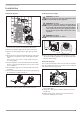
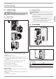
Scanning the error menu
The error menu only appears if the appliance has a fault.
D0000046156
1 2 3 4
1 Electronic assembly symbol
Replace the electronic assembly.
2 Safety circuit symbol
Check the AE3 connection; replace the AE3 if required.
3 Outlet sensor symbol
Check the outlet sensor connection; replace the outlet sensor
if required.
4 Motorised valve symbol
Check the motorised valve connection; replace the motorised
valve if required.
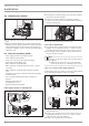
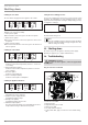
Scanning the control menu
26�02�02�1312�
1 2 3 4
1 Inlet temperature symbol,
shows the current inlet temperature (shows 1.0°C if the sen-
sor is faulty).
2 Outlet temperature symbol,
shows the current outlet temperature (shows 65.0°C if the
sensor is faulty).
3 Flow rate symbol,
shows the current flow rate.
4 Power consumption symbol,
shows the current power consumption.
Scanning the appliance data menu
26�02�02�1314�
1 2 3 4
1 Service code symbol,
information for service engineers.
2 Symbol for power supply runtime,
accumulated runtime in days.
3 Heating hours symbol,
accumulated heating time in hours.
4 Maximum output symbol
The value shown may diverge by several kW from the rated
output if mains voltages other than 400V prevail.
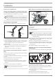
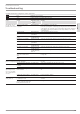
Setting the anti-scalding protection
Use the anti-scalding protection in places such as nurseries and
hospitals. The temperature set here simultaneously acts as the
upper limit of the temperature setting for childproofing (see chap-
ter “Appliance settings”).
26�02�02�1301�
Setting range: 21 - 60°C
Recommended setting 43°C
Note
The anti-scalding protection setting can only be modified
by your contractor. Simultaneously pressing the M + i key
will not change the setting.
13. Shutting down
Isolate all poles of the appliance from the power supply.
Drain the appliance (see chapter "Maintenance").
14. Troubleshooting
WARNING Electrocution
In order to check the appliance, it must be supplied with
power.
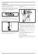
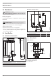
Plug-in connections on the PCB
26�02�02�1343
1
5
6
7
2
3
4
1 Diagnostic traffic light (3 LEDs)
2 Flow rate sensor DFE
3 Motorised valve
4 High limit safety cut-out STB
5 Outlet sensor NTC
6 Set temperature transducer
7 Safety switch AE 3; plug-in connection secured with locking
tab.