GEBRAUCHS- UND MONTAGEANLEITUNG OPERATING AND INSTALLATION INSTRUCTIONS INSTRUCTIONS D‘UTILISATION ET DE MONTAGE GEBRUIKS- EN MONTAGEAANWIJZING NÁVOD K POUŽÍVÁNÍ A MONTÁŽI INSTRUKCJA OBSŁUGI I MONTAŻU Vollelektronisch geregelter Durchlauferhitzer | Instantaneous water heater with full electronic control | Chauffe-eau instantané à régulation entièrement électronique | Volledig elektronisch geregelde elektrische doorstromer | Plně elektronicky regulovaný průtokový ohřívač | Caikowicie elektronicznie regulowan
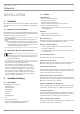
INHALT | BEDIENUNG Allgemeine Hinweise BEDIENUNG 1. 1.1 1.2 1.3 Allgemeine Hinweise ����������������������������������������2 Sicherheitshinweise ��������������������������������������������� 2 Andere Markierungen in dieser Dokumentation ���������� 3 Maßeinheiten ����������������������������������������������������� 3 2. 2.1 2.2 2.
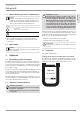
1.2 Andere Markierungen in dieser Dokumentation Hinweis Hinweise werden durch horizontale Linien ober- und unterhalb des Textes begrenzt. Allgemeine Hinweise werden mit dem nebenstehenden Symbol gekennzeichnet. ff Lesen Sie die Hinweistexte sorgfältig durch. ! Symbol ! Sachschaden (Geräte-, Folge-, Umweltschaden) Geräteentsorgung ff Dieses Symbol zeigt Ihnen, dass Sie etwas tun müssen. Die erforderlichen Handlungen werden Schritt für Schritt beschrieben. 1.
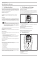
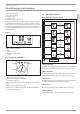
BEDIENUNG Gerätebeschreibung 3. Gerätebeschreibung Das vollelektronisch geregelte Gerät mit automatischer Leistungsanpassung hält die Auslauftemperatur konstant. Das Wasser wird durch die vollelektronische Regelung mit Motorventil gradgenau auf die eingestellte Temperatur erwärmt. Dies geschieht unabhängig von der Zulauftemperatur. Warmwassertemperatur 4. Einstellungen und Anzeigen Sie können das Gerät am Bedienfeld einstellen.
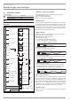
BEDIENUNG Einstellungen und Anzeigen Sparmonitor aufrufen Menüstruktur am Beispiel in Euro (Eur) Bei Lieferung ist die Hintergrundbeleuchtung so eingestellt, dass sich die Beleuchtung automatisch einschaltet, sobald Sie den Einstellknopf oder eine Taste betätigen oder das Gerät heizt. Nach 30 Sekunden ohne Betätigung oder ohne Heizbetrieb schaltet sich die Hintergrundbeleuchtung aus. Sie können auch auf Dauerbeleuchtung stellen. Reset M 2 sec. M 2 sec. Reset M 4.2 26_02_02_1230_ 5 2 sec.
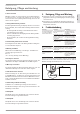
BEDIENUNG Einstellungen und Anzeigen 4.4 Einstellungen am Gerät 1 ECO Wasser- und Energiesparfunktion Mit der ECO-Funktion können Sie die Durchflussmenge auf einen Maximalwert begrenzen.
BEDIENUNG Reinigung, Pflege und Wartung Wahlweise können Sie sich die Uhrzeit oder die Durchflussmenge anzeigen lassen. Sie können die Uhrzeit von 00:00 bis 23:59 einstellen. Nach einer Spannungsunterbrechung müssen Sie die Uhrzeit erneut eingeben. 7 Hintergrundbeleuchtung einstellen Die Hintergrundbeleuchtung des Displays können Sie einstellen. Bei der Auswahl „Auto“ blinkt die Beleuchtung während der Einstellung. -- Die Hintergrundbeleuchtung ist beim Heizbetrieb und bei jeder Bedienung eingeschaltet.
INSTALLATION Sicherheit INSTALLATION 7. Sicherheit Die Installation, Inbetriebnahme sowie Wartung und Reparatur des Gerätes darf nur von einem Fachhandwerker durchgeführt werden. 7.1 Allgemeine Sicherheitshinweise Wir gewährleisten eine einwandfreie Funktion und Betriebssicherheit nur, wenn das für das Gerät bestimmte Original-Zubehör und die Original-Ersatzteile verwendet werden. ! 7.2 Sachschaden Beachten Sie die maximale Zulauftemperatur.
INSTALLATION Vorbereitungen Vorbereitungen Untertischmontage DEUTSCH 9. ff Spülen Sie die Wasserleitung gut durch. Armaturen ff Verwenden Sie geeignete Armaturen (siehe Kapitel „Gerätebeschreibung / Zubehör“). Offene Armaturen sind nicht zulässig. Hinweis Das Kreuzstück darf nicht zum Drosseln des Volumenstromes verwendet werden. Es dient zur Absperrung des Gerätes.
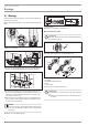
INSTALLATION Montage 10. Montage 160 1 30 26_02_02_0824_ In diesem Kapitel wird die Montage entsprechend der Werkseinstellungen beschrieben. Weitere Montagemöglichkeiten siehe Kapitel „Montage-Alternativen“. 1 Montagehilfe ff Richten Sie das Netzanschlusskabel her. Wasseranschluss herstellen Sachschaden Führen Sie alle Wasseranschluss- und Installationsarbeiten nach Vorschrift aus. 26_02_02_0543 ! D0000053319 12 ff Öffnen Sie das Gerät.
INSTALLATION Montage WARNUNG Stromschlag Führen Sie alle elektrischen Anschluss- und Installationsarbeiten nach Vorschrift aus. WARNUNG Stromschlag Der Anschluss an das Stromnetz ist nur als fester Anschluss in Verbindung mit der herausnehmbaren Kabeltülle erlaubt. Das Gerät muss über eine Trennstrecke von mindestens 3 mm allpolig vom Netzanschluss getrennt werden können.
INSTALLATION Montage 10.1 Montage abschließen ff Montieren Sie das Rückwandunterteil. Achten Sie darauf, dass das Rückwandunterteil einrastet. ff Richten Sie das montierte Gerät aus, indem Sie den Befestigungsknebel lösen, den Elektroanschluss und die Rückwand ausrichten und den Befestigungsknebel wieder festdrehen. Liegt die Geräterückwand nicht an, können Sie das Gerät unten mit einer zusätzlichen Schraube befestigen. 10.
INSTALLATION Montage ! Sachschaden Schließen Sie die Phase, die das Lastabwurfrelais schaltet, an die gekennzeichnete Klemme der Netzanschlussklemme im Gerät an (siehe Kapitel „Technische Daten / Elektroschaltplan“). 4 3 2 1 D0000041391 Setzen Sie das Lastabwurfrelais in Kombination mit anderen Elektrogeräten, z. B. Elektrospeicherheizgeräten, in der Elektroverteilung ein. Der Lastabwurf erfolgt bei Betrieb des Durchlauferhitzers. Das Lastabwurfrelais erhalten Sie als Zubehör.
INSTALLATION Montage Aufhängeleiste bei Geräteaustausch Gedrehte Gerätekappe Eine vorhandene Aufhängeleiste von Stiebel Eltron kann bei Geräteaustausch evtl. verwendet werden (Ausnahme Durchlauferhitzer DHF). ff Durchstoßen Sie die Rückwand des Gerätes für den Gewindebolzen auf der bereits montierten Aufhängeleiste. Die Gerätekappe kann bei einer Untertischmontage gedreht werden.
11. Inbetriebnahme WARNUNG Stromschlag Die Inbetriebnahme darf nur durch einen Fachhandwerker unter der Beachtung der Sicherheitsvorschriften erfolgen. ff Weisen Sie den Benutzer auf mögliche Gefahren hin, speziell die Verbrühungsgefahr. ff Übergeben Sie diese Anleitung. 11.2 Wiederinbetriebnahme ! 11.1 Erstinbetriebnahme ff Öffnen Sie das Kreuzstück.
INSTALLATION Außerbetriebnahme Error-Menü abfragen D0000046156 Das Error-Menü erscheint nur, wenn Fehler im Gerät vorhanden sind. 1 2 3 4 1 Symbol elektronische Baugruppe ff Tauschen Sie die elektronische Baugruppe. 2 Symbol Sicherheitskreis ff Überprüfen Sie die Verbindung vom AE 3, tauschen Sie ggf. den AE 3. 3 Symbol Auslauffühler ff Überprüfen Sie die Verbindung vom Auslauffühler, tauschen Sie ggf. den Auslauffühler.
INSTALLATION Störungsbehebung Störung Ursache Das Gerät heizt nicht Es liegt keine Netzspannung auf / die Solltempera- an. tur wird nicht erreicht. Der Sicherheitsschalter (AE3) hat ausgelöst. Das Display im Gerät ist komplett aus. DEUTSCH Anzeigemöglichkeiten der Diagnoseampel (LED) rot leuchtet bei Störung gelb leuchtet bei Heizbetrieb grün blinkt: Gerät am Netzanschluss Diagnoseampel keine LED leuchtet Behebung Überprüfen Sie die Sicherung in der Hausinstallation.
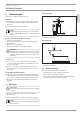
INSTALLATION Wartung 15. Wartung Alternative Anschlussmöglichkeiten WARNUNG Stromschlag Trennen Sie bei allen Arbeiten das Gerät allpolig vom Netzanschluss. b04 47 338 Das Gerät können Sie für Wartungsarbeiten oder zum Schutz vor Frost entleeren. VORSICHT Verbrühung Beim Entleeren des Gerätes kann heißes Wasser austreten. b04 b02 30 16. Technische Daten 16.1 Maße und Anschlüsse D0000019212 44 ff Schließen Sie das Absperrventil in der Kaltwasser-Zulaufleitung.
INSTALLATION Technische Daten siehe auch Kapitel „Gerätebeschreibung / Zubehör“ Spezifischer elektrischer Widerstand und spezifische elektrische Leitfähigkeit, siehe „Datentabelle“. 85_02_02_0003_ 2 1 1 Steuerleitung zum Schaltschütz des 2. Gerätes (z. B. Elektrospeicherheizgerät). 2 Steuerkontakt öffnet beim Einschalten des Durchlauferhitzers. Die Werte sind auf eine Nennspannung von 400 V bezogen. Die Mischwassermenge bzw.
INSTALLATION Technische Daten 16.7 Angaben zum Energieverbrauch Die Produktdaten entsprechen den EU-Verordnungen zur Richtlinie für umweltgerechte Gestaltung energieverbrauchsrelevanter Produkte (ErP).
GARANTIE | UMWELT UND RECYCLING DEUTSCH Garantie Für außerhalb Deutschlands erworbene Geräte gelten nicht die Garantiebedingungen unserer deutschen Gesellschaften. Vielmehr kann in Ländern, in denen eine unserer Tochtergesellschaften unsere Produkte vertreibt, eine Garantie nur von dieser Tochtergesellschaft erteilt werden. Eine solche Garantie ist nur dann erteilt, wenn die Tochtergesellschaft eigene Garantiebedingungen herausgegeben hat. Darüber hinaus wird keine Garantie erteilt.
CONTENTS | OPERATION General information OPERATION OPERATION 1. 1.1 1.2 1.3 General information ��������������������������������������� 22 Safety instructions ���������������������������������������������� 22 Other symbols in this documentation ���������������������� 23 Units of measurement ����������������������������������������� 23 2. 2.1 2.2 2.
OPERATION Safety Other symbols in this documentation Note Notes are bordered by horizontal lines above and below the text. General information is identified by the symbol shown on the left. ff Read these texts carefully. Symbol ! Material damage (appliance, consequential and environmental damage) Appliance disposal Where children or persons with limited physical, sensory or mental abilities are allowed to use this appliance, we recommend a permanent temperature limit.
OPERATION Appliance description 3. Appliance description This appliance with full electronic control and output matching keeps the outlet temperature constant. The water is heated by the electronic control unit with motorised valve to precisely the selected temperature. This occurs regardless of the inlet temperature. DHW temperature The DHW outlet temperature can be variably adjusted. The selected temperature is displayed. 4. Settings and displays You can adjust the appliance via the user interface.
OPERATION Settings and displays 4.3 7 Temperature display 8 Service symbol 9 Fault symbol 10 Information key, economy menu Economy monitor selection Example menu structure with currency in euros (Eur) When the appliance is delivered the backlighting is set so that the screen is illuminated automatically as soon as you operate the selector or a key, or the appliance heats. If the selector or a key is not pressed or the appliance does not heat for 30 seconds, the backlighting switches off.
OPERATION Settings and displays 4.4 Appliance settings Key to symbols Press once Press once Hold for 2 seconds Change settings / scanning 1 ECO water and energy saving function The ECO function enables you to limit the flow rate to a maximum value. ECO on = symbol on user interface ECO off = no symbol on user interface START-menu Change menu END 2 Childproofing Childproofing allows you as a user to limit the adjustable temperature at the appliance to a maximum value.
OPERATION Cleaning, care and maintenance You are able to adjust the display backlighting. If you select "Auto" the illumination will flash during the setting process. -- The backlighting switches on whenever the appliance heats and with any operation of the user interface. -- If there is no operation for 30 seconds the backlighting switches off. -- If you select "On" the backlighting will remain on constantly.
INSTALLATION Safety INSTALLATION 7. Safety Only a qualified contractor should carry out installation, commissioning, maintenance and repair of the appliance. 7.1 General safety instructions We guarantee trouble-free function and operational reliability only if the original accessories and spare parts intended for the appliance are used. ! 7.2 Material damage Observe the maximum inlet temperature. The appliance can be damaged by higher temperatures.
INSTALLATION Preparations 9. Preparations Undersink installation ff Flush the water line thoroughly. Taps/valves ff Use suitable taps (see chapter "Appliance description / Accessories"). Open taps are not permitted. Note Never use the cross-piece to reduce the flow rate. It is intended to shut off the appliance.
INSTALLATION Installation 10. Installation 160 1 30 26_02_02_0824_ This chapter describes installation in accordance with the factory settings. For further installation options, see chapter "Installation alternatives". 1 Installation aid ff Prepare the power cable. Making the water connection Material damage Carry out all water connection and installation work in accordance with regulations. 26_02_02_0543 ! D0000053319 12 ff Open the appliance.
INSTALLATION Installation Connecting the power supply Installing the appliance WARNING Electrocution Connection to the power supply is only permissible in the form of a permanent connection in conjunction with the removable cable grommet. Ensure that the appliance can be separated from the power supply by an isolator that disconnects all poles with at least 3 mm contact separation. 18 21 24 kW ff Connect the power cable to the mains terminal (see chapter "Specification / Wiring diagram").
INSTALLATION Installation 10.1 Completing the installation ff Fit the lower part of the back panel. Ensure that it clicks into place. ff Align the mounted appliance by loosening the fixing toggle, aligning the power supply and back panel, and then re-tightening the fixing toggle. If the back panel of the appliance is not flush, the appliance can be secured at the bottom with an additional screw. 10.
INSTALLATION Installation Water installation for finished walls, fitting the appliance cover ! Material damage Connect the phase that switches the load shedding relay to the indicated terminal of the mains terminal in the appliance (see chapter "Specification / Wiring diagram"). 4 3 2 ENGLISH Install the load shedding relay in the distribution board in conjunction with other electric appliances, e.g. electric storage heaters. The relay responds when the instantaneous water heater starts.
INSTALLATION Installation Mounting bracket for appliance replacement Turned appliance cover Am existing Stiebel Eltron mounting bracket may be used when replacing appliances (except instantaneous water heater DHF). ff Break through the back panel of the appliance for the threaded stud on the pre-installed mounting bracket. The appliance cover can be turned for undersink installation.
INSTALLATION Commissioning 11. Commissioning WARNING Electrocution Commissioning may only be carried out by an authorised contractor in accordance with safety regulations. 11.1 Commissioning ff Open the cross-piece. ! Material damage Following an interruption of the water supply the appliance must be recommissioned by carrying out the following steps, in order to prevent the destruction of the bare wire heating system.
INSTALLATION Shutting down Setting the anti-scalding protection The error menu only appears if the appliance has a fault. Use the anti-scalding protection in places such as nurseries and hospitals. The temperature set here simultaneously acts as the upper limit of the temperature setting for childproofing (see chapter “Appliance settings”). 1 2 3 4 1 Electronic assembly symbol ff Replace the electronic assembly. 2 Safety circuit symbol ff Check the AE 3 connection; replace the AE 3 if required.
INSTALLATION Troubleshooting Fault Cause The appliance does not There is no mains voltage. heat up / the set temThe safety switch (AE 3) has perature is not reached. responded. The PCB is faulty. A phase has failed. The inlet temperature is > 55 °C. The flow rate sensor (DFE) is faulty or not attached. The heater is faulty. The inlet sensor is faulty. The outlet sensor is faulty. A fault in the safety PCB. A loose or faulty connecting cable to the set value transducer.
INSTALLATION Maintenance 15. Maintenance Alternative connection options WARNING Electrocution Before any work on the appliance, disconnect all poles from the power supply. b04 47 338 You can drain the appliance for maintenance work or to protect it from frost. CAUTION Scalding Hot water may escape when draining the appliance. 72 b04 ≤ 20 105 35 D0000019212 44 165 b04 b02 b03 b04 16.1 Dimensions and connections 225 140 50 ff Close the shut-off valve in the cold water supply line.
INSTALLATION Specification 16.4 Applications / Conversion table Priority control with load shedding relay (LR 1-A) See also chapter "Appliance description / Accessories". 85_02_02_0003_ 2 1 Standard specification at 15 °C 20 °C Spec. Resi- Spec. Con- Spec. Spec.
INSTALLATION Specification 16.7 Details on energy consumption Product data complies with EU regulations relating to the Directive on the ecodesign of energy related products (ErP).
GUARANTEE | ENVIRONMENT AND RECYCLING Guarantee ENGLISH The guarantee conditions of our German companies do not apply to appliances acquired outside of Germany. In countries where our subsidiaries sell our products a guarantee can only be issued by those subsidiaries. Such guarantee is only granted if the subsidiary has issued its own terms of guarantee. No other guarantee will be granted.
TABLE DES MATIÈRES | UTILISATION Remarques générales UTILISATION UTILISATION 1. 1.1 1.2 1.3 Remarques générales ������������������������������������� 42 Consignes de sécurité ������������������������������������������ 42 Autres repérages utilisés dans cette documentation ���� 43 Unités de mesure ����������������������������������������������� 43 2. 2.1 2.2 2.
UTILISATION Sécurité Autres repérages utilisés dans cette documentation ! Remarque Les remarques sont délimitées par des lignes horizontales au-dessus et en dessous du texte. Le symbole ci-contre caractérise des remarques générales. ff Lisez attentivement les remarques. Symbole ! Dommages matériels (dégâts induits, dommages causés à l’appareil, à l’environnement ) Recyclage de l’appareil ff Ce symbole indique une action à entreprendre. Les actions nécessaires sont décrites étape par étape. 1.
UTILISATION Description de l’appareil 3. Description de l’appareil Ce chauffe-eau à régulation entièrement électronique ajuste automatiquement sa puissance pour maintenir une température de sortie de l’eau constante. Une vanne motorisée commandée par la régulation électronique permet de maintenir l’eau à la température de consigne avec une grande précision, quelle que soit de la température d’arrivée d’eau. Température ECS 4.
UTILISATION Réglages et affichages 4.3 6 Affichage de la puissance de chauffe 7 Affichage de la température 8 Icône S A V 9 Icône Défaut 10 Touche d’information - menu Économies Demande d’affichage de l’éco-surveillance Structure de menu, exemple en euros (Eur) À la livraison, le rétro-éclairage est réglé de manière à ce qu’il s’allume automatiquement lorsque l’on manipule le bouton de réglage ou une touche ou lorsque l’appareil est en chauffe.
UTILISATION Réglages et affichages 4.4 Réglages sur l’appareil 1 Fonction ECO eau et énergie Cette fonction ECO permet de limiter le débit à une valeur maximale.
UTILISATION Nettoyage, entretien et maintenance 7 Réglage du rétro-éclairage Le rétro-éclairage de l’écran est réglable. Si vous choisissez « Auto », l’éclairage clignote pendant le réglage. -- Le rétro-éclairage est allumé pendant que l’eau chauffe et à chaque manipulation. -- Il s’éteint après 30 secondes s’il n’y a pas eu d’intervention. -- Sur « On », le rétro-éclairage reste allumé en permanence.
INSTALLATION Sécurité INSTALLATION 7. Sécurité Le montage, la mise en service, la maintenance et les réparations de cet équipement ne doivent être effectués que par un installateur qualifié. 7.1 Consignes de sécurité générales Nous ne garantissons le bon fonctionnement et la sécurité de l’appareil que si les accessoires et pièces de rechange d’origine sont employés. ! 7.2 Dommages matériels Tenez compte de la température maximale d’arrivée d’eau.
INSTALLATION Travaux préparatoires 9. Travaux préparatoires Pose sous plan de travail ff Rincez soigneusement la conduite d’eau. Robinetterie ff Utilisez des robinetteries appropriées (voir le chapitre « Description de l’appareil / Accessoires »). Les robinetteries à écoulement libre ne sont pas autorisées.
INSTALLATION Pose 10. Pose 160 1 30 26_02_02_0824_ Ce chapitre décrit la pose de l’appareil conformément aux réglages usine. Pour les autres possibilités de pose, voir le chapitre « Variantes de pose ». 1 Accessoire de pose ff Ajustez le câble d’alimentation. Réalisation du raccordement hydraulique Dommages matériels Exécutez tous les travaux de raccordement et d’installation hydrauliques suivant les prescriptions. 26_02_02_0543 ! D0000053319 12 ff Ouvrez l’appareil.
INSTALLATION Pose Raccordement électrique Pose de l’appareil AVERTISSEMENT Électrocution Exécutez tous les travaux de raccordement et d’installation électriques conformément aux prescriptions. AVERTISSEMENT Électrocution Le raccordement au secteur n’est autorisé que sous forme d’une connexion fixe réalisée en liaison avec le passecâble amovible. L’appareil doit pouvoir être déconnecté du secteur par un dispositif de coupure multipolaire ayant une ouverture minimale des contacts de 3 mm.
INSTALLATION Pose 10.1 Fin de la pose 10.
INSTALLATION Pose 1. ff Montez la robinetterie. ff Posez la partie inférieure de la paroi arrière sous les conduites de raccordement de la robinetterie puis insérez-la dans la paroi arrière. ff Vissez les conduites de raccordement à l’appareil. 2. Installation hydraulique en applique avec raccord à souder / à sertir 4. 26_02_02_1124_ 3. ff Avant le montage de l’appareil, appuyez sur le passe-câble à l’aide d’un tournevis pour le sortir.
INSTALLATION Pose ff Fixez la paroi arrière en bas avec une vis. Installation avec déport de carrelage Montage de la partie inférieure de la paroi arrière avec raccords filetés en applique 20 2 Vous pouvez mettre en place la partie inférieure de la paroi arrière une fois la robinetterie installée. 2 26_02_02_1066_ 110 1 26_02_02_1080 1 1 Vis 2 Pièces de raccordement fournies ff Sciez la partie inférieure de la paroi arrière selon les repères.
INSTALLATION Mise en service L’installation d’une robinetterie thermostatique centralisée permet de limiter la température a une valeur maximale (voir chapitre « Description de l’appareil / Accessoires). 11. Mise en service AVERTISSEMENT Électrocution La mise en service doit être réalisée par un installateur en respectant les prescriptions de sécurité. 11.1 Première mise en service ff Ouvrez la vanne en croix.
INSTALLATION Mise hors service Consultation du menu des erreurs D0000046156 Le menu des erreurs n’apparaît que si l’appareil présente un défaut de fonctionnement. 1 2 3 4 1 Icône module électronique ff Remplacez le module électronique. 2 Icône circuit de sécurité ff Vérifiez la connexion du AE 3, remplacez-le éventuellement. 3 Icône sonde de sortie ff Vérifiez la connexion de la sonde de sortie, remplacez-la éventuellement.
INSTALLATION Aide au dépannage Différents affichages possibles des voyants de diagnostic (LED) rouge allumée en présence d’une panne jaune allumée en mode chauffage vert clignote : appareil raccordé au secteur Panne Cause Voyant de diagnostic Solution L’appareil ne chauffe pas / impossible d’atteindre la température de consigne. L’appareil n’est pas sous tension secteur. Le thermostat de sécurité (AE3) s’est déclenché.
INSTALLATION Maintenance 15. Maintenance Autres branchements possibles AVERTISSEMENT Électrocution Déconnectez tous les pôles d’alimentation secteur de l’appareil avant toute intervention. b04 47 338 Vous pouvez vidanger l’appareil pour les opérations de maintenance ou pour le protéger du gel. ATTENTION Brûlure L’eau sortant de l’appareil lors de la vidange peut être très chaude. b04 b02 30 165 b04 b02 b03 b04 16.
INSTALLATION Données techniques 16.4 Plages d’utilisation / Tableau de conversion voir également le chapitre « Description de l’appareil / Accessoires » 85_02_02_0003_ 2 1 1 Câble de commande vers le contacteur du 2e appareil (chauffage électrique à accumulation p. ex.). 2 Le contact de commande s’ouvre lorsque le chauffe-eau instantané s’enclenche. Les valeurs se basent sur une tension nominale de 400 V.
INSTALLATION Données techniques 16.7 Indications relatives à la consommation énergétique Les caractéristiques produit correspondent aux prescriptions de la directive UE sur l’éco-conception applicable aux produits liés à l’énergie (EuP).
GARANTIE | ENVIRONNEMENT ET RECYCLAGE Garantie Les conditions de garantie de nos sociétés allemandes ne s’appliquent pas aux appareils achetés hors d’Allemagne. Au contraire, c’est la filiale chargée de la distribution de nos produits dans le pays qui est seule habilitée à accorder une garantie. Une telle garantie ne pourra cependant être accordée que si la filiale a publié ses propres conditions de garantie. Il ne sera accordé aucune garantie par ailleurs.
INHOUD | BEDIENING Algemene aanwijzingen BEDIENING 1. 1.1 1.2 1.3 Algemene aanwijzingen ����������������������������������� 62 Veiligheidsaanwijzingen �������������������������������������� 62 Andere aandachtspunten in deze documentatie ��������� 63 Maateenheden �������������������������������������������������� 63 2. 2.1 2.2 2.
BEDIENING Veiligheid Andere aandachtspunten in deze documentatie Info Aanwijzingen worden door horizontale lijnen boven en onder de tekst begrensd. Algemene aanwijzingen worden aangeduid met het symbool dat hiernaast staat. ff Lees de aanwijzingsteksten grondig door. ! Symbool ! Materiële schade (toestel-, gevolg-, milieuschade) Het toestel afdanken ff Dit symbool geeft aan dat u iets moet doen. De vereiste handelingen worden stapsgewijs beschreven. 1.
BEDIENING Toestelbeschrijving 3. Toestelbeschrijving Het volledig elektronische geregelde toestel met automatische vermogensaanpassing houdt de uitlooptemperatuur constant. Het water wordt door de volledig elektronische regeling met motorklep tot op de graad nauwkeurig op de ingestelde temperatuur opgewarmd. Dit gebeurt onafhankelijk van de aanvoertemperatuur. Warmwatertemperatuur 4. Instellingen en weergaven U kunt het toestel op het bedieningspaneel instellen.
BEDIENING Instellingen en weergaven 4.3 7 Indicator Temperatuur 8 Symbool Service 9 Symbool Storing 10 Infotoets-spaarmenu Besparingsmonitor oproepen Menustructuur in het voorbeeld in euro (Eur) Bij levering is de achtergrondverlichting op een wijze ingesteld dat de verlichting automatisch inschakelt, zodra u de instelknop of een toets bedient, of als het toestel opwarmt. Na 30 seconden zonder bediening of zonder verwarmingsfunctie schakelt de achtergrondverlichting uit.
BEDIENING Instellingen en weergaven 4.4 Instellingen op het toestel Verklaring van de symbolen 1 x drukken 1 x drukken 2 seconden drukken Instellingen/opvraging wisselen 1 ECO-water- en energiespaarfunctie Met de ECO-functie is het mogelijk het doorstroomvolume tot een maximumwaarde te begrenzen.
BEDIENING Reiniging, verzorging en onderhoud U kunt naar keuze de tijd of het doorstroomvolume laten weergeven. U kunt de tijd van 00:00 tot 23:59 instellen. Na een spanningsonderbreking moet u de kloktijd opnieuw invoeren. 7 Achtergrondverlichting instellen U kunt de achtergrondverlichting van het display instellen. Bij de selectie "Auto" knippert de verlichting tijdens de instelling. -- De achtergrondverlichting is bij elke verwarmingsfunctie en bij elke bediening ingeschakeld.
INSTALLATIE Veiligheid INSTALLATIE 7. Veiligheid Installatie, ingebruikname, evenals onderhoud en reparatie van het toestel mogen alleen door een gekwalificeerde installateur uitgevoerd worden. 7.1 Algemene veiligheidsaanwijzingen Wij waarborgen de goede werking en de bedrijfszekerheid uitsluitend bij gebruik van originele accessoires en onderdelen voor het toestel. ! 7.2 Materiële schade Houd rekening met de maximale aanvoertemperatuur. Bij hogere temperaturen kan het toestel beschadigd raken.
INSTALLATIE Voorbereidingen ZTA 3/4 - centrale thermostaatkraan Montage onder de wastafel Thermostaatkraan voor centrale voormenging, bijvoorbeeld van een doorstroomverwarmer met een zonne-installatie. 9. Voorbereidingen ff Spoel de waterleiding grondig door. 1 2 Een veiligheidsklep is niet vereist.
INSTALLATIE Montage 10. Montage 160 1 30 26_02_02_0824_ In dit hoofdstuk wordt de montage overeenkomstig de fabrieksinstellingen beschreven. Zie voor meer montagemogelijkheden het hoofdstuk "Montageopties". 1 Montagehulp ff Lijn de netaansluitkabel uit. Wateraansluiting tot stand brengen Materiële schade Voer alle werkzaamheden voor wateraansluiting en installatie uit conform de voorschriften. 26_02_02_0543 ! D0000053319 12 ff Open het toestel.
INSTALLATIE Montage Elektriciteit aansluiten Toestel monteren WAARSCHUWING elektrische schok Voer alle werkzaamheden voor elektriciteitsaansluitingen en installatie uit conform de voorschriften. WAARSCHUWING elektrische schok De aansluiting op het stroomnet is alleen toegestaan als vaste aansluiting in combinatie met de uitneembare kabeldoorvoer. Het toestel moet op alle polen met een afstand van minstens 3 mm van de netaansluiting kunnen worden losgekoppeld.
INSTALLATIE Montage 10.1 Montage afsluiten ff Monteer het onderstuk van de achterwand. Let erop dat het onderstuk van de achterwand vergrendelt. ff Lijn het gemonteerde toestel uit door de bevestigingsknevel los te maken, de elektrische aansluiting en de achterwand uit te lijnen en de bevestigingsknevel weer vast te draaien. Als de achterwand van het toestel niet goed tegen de wand komt, kunt u het toestel onderaan met een extra schroef bevestigen. 10.
INSTALLATIE Montage ff Schuif de kabeldoorvoer over de elektrische aansluitkabel. Gebruik daarvoor de montagehulp. Vergroot bij een diameter van > 6 mm² het gat in de kabeldoorvoer. ff Schuif de kabeldoorvoer in de achterwand. Aansluiting van een lastafwerprelais Waterinstallatie opbouw, montage van de bovenkap 3 2 1 Waterinstallatie opbouw Geschikte drukkranen zijn verkrijgbaar u als toebehoren.
INSTALLATIE Montage ff Monteer het onderstuk van de achterwand door het zijdelings open te buigen en over de opbouwbuizen te steken. ff Steek de verbindingsstukken achterlangs in het onderstuk van de achterwand. ff Zet het onderstuk van de achterwand vast in de achterwand. ff Bevestig het onderstuk van de achterwand met een schroef. Gedraaide bovenkap De bovenkap kan worden gedraaid bij montage onder het aftappunt.
INSTALLATIE Ingebruikname 11. Ingebruikname ff Overhandig deze handleiding. WAARSCHUWING elektrische schok De ingebruikname mag alleen uitgevoerd worden door een installateur die rekening houdt met alle veiligheidsvoorschriften. 11.1 Eerste ingebruikname ff Open het kruisstuk. on 11.2 Opnieuw in gebruik nemen ! Materiële schade Als de watervoorziening onderbroken is geweest, moet het toestel via de volgende stappen opnieuw in gebruik worden genomen, zodat het blankdraadelement niet kapot gaat.
INSTALLATIE Buitendienststelling Verbrandingsbeveiliging instellen Menu Error verschijnt alleen, wanneer er een fout in het toestel opgetreden is. Gebruik deze verbrandingsbeveiliging, bijv. in kleuterscholen, ziekenhuizen, enz. De hier ingestelde temperatuur is tevens de bovengrens voor de temperatuurinstelling van de kinderbeveiliging (zie hoofdstuk „Instellingen op het toestel“).
INSTALLATIE Storingen verhelpen Weergavemogelijkheden diagnosestoplicht (LED) rood is bij storing verlicht geel is tijdens de verwarmingsfunctie verlicht groen knippert: Toestel met netaansluiting Oorzaak Er is geen netspanning. Veiligheidsschakelaar (AE3) heeft gewerkt. Oplossing Controleer de zekering in de huisinstallatie. Los de oorzaak van de fout op. Bescherm het verwarmingssysteem tegen oververhitting door een voorbij het toestel geschakelde aftapkraan gedurende één minuut open te zetten.
INSTALLATIE Onderhoud 15. Onderhoud Optionele aansluitmogelijkheden WAARSCHUWING elektrische schok Scheid alle polen van het toestel van het elektriciteitsnet voor aanvang van alle werkzaamheden. b04 47 338 U kunt het toestel voor onderhoudswerkzaamheden of ter bescherming tegen vorst aftappen. VOORZICHTIG Verbranding Tijdens het aftappen van het toestel kan er heet water uitlopen. b04 b02 30 165 b04 b02 b03 b04 16.
INSTALLATIE Technische gegevens 16.4 Toepassingsmogelijkheden / Herleidingtabel Voorrangschakeling met lastafwerprelais (LR 1-A) zie ook hoofdstuk "Toestelbeschrijving/toebehoren" Specifieke elektrische weerstand en specifieke elektrische geleidbaarheid, zie “Gegevenstabel “. 1 Besturingskabel voor het relais van het 2e toestel (bijv. elektrische boilerverwarming). 2 Besturingscontact gaat open als de doorstroomverwarmer inschakelt. 16.
INSTALLATIE Technische gegevens 16.7 Gegevens over het energieverbruik De productgegevens voldoen aan de EU-verordeningen betreffende de richtlijn voor milieuvriendelijke vormgeving van energiegerelateerde producten (ErP).
GARANTIE | MILIEU EN RECYCLING Garantie Voor toestellen die buiten Duitsland zijn gekocht, gelden de garantievoorwaarden van onze Duitse ondernemingen niet. Bovendien kan in landen waar één van onze dochtermaatschappijen verantwoordelijk is voor de verkoop van onze producten, alleen garantie worden verleend door deze dochtermaatschappij. Een dergelijk garantie wordt alleen verstrekt, wanneer de dochtermaatschappij eigen garantievoorwaarden heeft gepubliceerd.
OBSAH | OBSLUHA Obecné pokyny OBSLUHA OBSLUHA 1. 1.1 1.2 1.3 Obecné pokyny ��������������������������������������������� 82 Bezpečnostní pokyny ������������������������������������������ 82 Jiné symboly použité v této dokumentaci ������������������ 83 Měrné jednotky ������������������������������������������������� 83 2. 2.1 2.2 2.
OBSLUHA Bezpečnost 1.2 Jiné symboly použité v této dokumentaci Upozornění Pokyny jsou odděleny vodorovnými čarami nad a pod textem. Všeobecné pokyny jsou označeny symbolem zobrazeným vedle. ff Texty upozornění čtěte pečlivě. Symbol ! Věcné škody (poškození přístroje, následné škody, škody na životním prostředí) Likvidace přístroje Pokud přístroj používají děti nebo osoby s omezenými tělesnými, senzorickými nebo duševními schopnostmi, doporučujeme trvalé omezení teploty.
OBSLUHA Popis přístroje 3. Popis přístroje Plně elektronicky regulovaný přístroj s automatickou úpravou výkonu udržuje konstantní výstupní teplotu vody. Plně elektronický regulační systém v součinnosti se servoventilem zajišťuje ohřev vody na přesně nastavenou teplotu. Tato funkce probíhá nezávisle na vstupní teplotě vody. Teplota teplé vody 4. Nastavení a zobrazení Přístroj můžete nastavit pomocí ovládacího panelu.
OBSLUHA Nastavení a zobrazení 4.3 8 Symbol servisu 9 Symbol chyby 10 Informační tlačítko - nabídka úsporného programu Vyvolání funkce monitoru úspor Struktura nabídek na příkladu v eurech (EMU) Při dodání je nastaveno podsvícení displeje tak, aby se automaticky rozsvítilo, jakmile použijete nastavovací regulátor, stisknete některé z tlačítek, nebo pokud přístroj ohřívá. Po 30 sekundách bez stisknutí jakéhokoliv tlačítka nebo bez ohřevu podsvícení zhasne. Podsvícení můžete přepnout i na trvalé svícení.
OBSLUHA Nastavení a zobrazení 4.4 Nastavení na přístroji Vysvětlivky symbolů 1 stisknutí 1 stisknutí Stisknutí a podržení 2 sekundy Přepnutí nastavení / kontrola 1 Funkce ECO - úspora energie a vody Pomocí funkce ECO můžete omezit maximální průtočné množství. ECO zap = symbol na ovládacím panelu ECO vyp = bez symbolu na ovládacím panelu START-nabídky Přepnutí nabídky KONEC 2 Dětská pojistka Dětská pojistka umožňuje uživateli omezit maximální teplotu nastavitelnou na přístroji.
OBSLUHA Čištění, péče a údržba Můžete nastavit podsvícení displeje. Při výběru možnosti „Auto“ bliká osvětlení během nastavování. -- Podsvícení se rozsvítí v režimu ohřevu a při každé manipulaci s ovládáním. -- Po uplynutí 30 sekund bez stisknutí tlačítka podsvícení zhasne. -- Při výběru možnosti „On“ svítí podsvícení trvale. 8 Nastavení intenzity barvy zelená/jantarová Jas obou barev podsvícení můžete upravit podle vlastních požadavků.
INSTALACE Bezpečnost INSTALACE 7. Bezpečnost Instalaci, uvedení do provozu, údržbu a opravy přístroje smí provádět pouze specializovaný odborník. 7.1 Všeobecná bezpečnostní upozornění Řádnou funkci a spolehlivý provoz lze zaručit pouze v případě použití originálního příslušenství a originálních náhradních dílů určených pro tento přístroj. ! 7.2 Věcné škody Dodržujte maximální vstupní teplotu. Při vyšších teplotách může dojít k poškození přístroje.
INSTALACE Příprava 9. Příprava Montáž pod umyvadlo ff Důkladně vypláchněte vodovodní vedení. Armatury ff Použijte vhodné armatury (viz kapitolu „Popis přístroje / Příslušenství“). Otevřené armatury nejsou dovolené. Upozornění Křížová tvarovka se nesmí používat ke škrcení objemového průtoku. Slouží k uzavření přístroje.
INSTALACE Montáž 10. Montáž 160 1 30 26_02_02_0824_ V této kapitole je uveden popis montáže v souladu s výrobním nastavením. Další možnosti montáže viz kapitolu „Alternativní postupy montáže“. 1 Montážní pomůcka ff Upravte přívodní kabel. Instalace vodovodní přípojky Věcné škody Veškeré vodovodní přípojky a instalace provádějte podle předpisů. 26_02_02_0543 ! D0000053319 12 ff Otevřete přístroj. 26_02_02_1101 ff Utěsněte a našroubujte dvojitou vsuvku.
INSTALACE Montáž Připojení přívodu elektrické energie Montáž přístroje VÝSTRAHA elektrický proud Veškerá elektrická zapojení a instalace provádějte podle předpisů. VÝSTRAHA elektrický proud Přípojka k elektrické síti smí být provedena pouze jako pevná přípojka v kombinaci s vyjímatelnou kabelovou vsuvkou. Přístroj musí být možné odpojit od síťové přípojky na všech pólech na vzdálenost minimálně 3 mm. VÝSTRAHA elektrický proud Pamatujte, že přístroj musí být připojen k ochrannému vodiči.
INSTALACE Montáž 10.1 Dokončení montáže ff Namontujte spodní díl zadní stěny. Dbejte na to, aby spodní díl zadní stěny dobře zapadl. ff Vyrovnejte namontovaný přístroj povolením upevňovací páčky, vyrovnejte elektrickou přípojku a zadní stěnu a opět utáhněte upevňovací páčku. Pokud zadní stěna přístroje nepřiléhá, můžete přístroj dole upevnit dalším šroubem. 10.
INSTALACE Montáž Vodovodní instalace na zdi, montáž víka přístroje Zátěžové relé používejte v kombinaci s jinými elektrickými přístroji v elektrickém rozvodu, například s elektrickými akumulačními ohřívači. K vypnutí zátěže dochází při provozu průtokového ohřívače. Zátěžové relé dodáváme jako příslušenství. Věcné škody Připojte fázi, která spíná zátěžové relé, k označené svorce síťové svorkovnice v přístroji (viz kapitolu „Technické údaje / Schéma elektrického zapojení“).
INSTALACE Montáž Závěsná lišta při výměně přístroje Otočené víko přístroje Stávající závěsnou lištu od výrobce Stiebel Eltron můžete případně použít při výměně přístroje (výjimkou je průtokový ohřívač DHF). ff Prorazte zadní stěnu přístroje pro závitový svorník na již namontované závěsné liště. Víko přístroje můžete při montáži pod umyvadlo otočit.
INSTALACE Uvedení do provozu 11. Uvedení do provozu 11.2 Opětovné uvedení do provozu VÝSTRAHA elektrický proud Uvedení do provozu smí provádět pouze specializovaný odborník při dodržení bezpečnostních předpisů. 11.1 První uvedení do provozu ff Otevřete křížovou tvarovku. on ! Věcné škody Po přerušení dodávky vody je nutné přístroj opětovně uvést do provozu pomocí následujících kroků, aby nedošlo k poškození topného systému s holou spirálou. ff Odpojte přístroj od napětí vypnutím pojistek.
INSTALACE Uvedení mimo provoz 1 2 3 4 1 Symbol elektronické konstrukční skupiny ff Vyměňte elektronickou konstrukční skupinu. 2 Symbol bezpečnostního obvodu ff Zkontrolujte připojení AE 3, příp. AE 3 vyměňte. 3 Symbol výstupního čidla ff Zkontrolujte připojení výstupního čidla, příp. čidlo vyměňte. 4 Symbol servoventilu ff Zkontrolujte připojení servoventilu, příp. servoventil vyměňte. Tuto ochranu proti opatření používejte například v mateřských školkách, nemocnicích apod.
INSTALACE Odstraňování poruch Možnosti zobrazení informací na diagnostické liště (LED) červená svítí při poruše žlutá svítí při ohřívání zelená bliká: Přístroj připojený k síti Závada Příčina Diagnostická lišta Odstranění Přístroj neohřívá / není dosaženo požadované teploty. Není připojeno elektrické napájení. Bezpečnostní spínač (AE3) vypnul. Nesvítí žádná LED Zkontrolujte pojistky v domovní instalaci. Nesvítí žádná LED Závada elektronického systému. Výpadek fáze.
INSTALACE Údržba 15. Údržba Alternativní možnosti připojení VÝSTRAHA elektrický proud Při všech činnostech odpojte přístroj na všech pólech od sítě. b04 47 b03 Vyprázdnění přístroje POZOR opaření Při vypouštění přístroje může vytékat horká voda. b04 16. Technické údaje 225 140 ≤ 20 D0000019212 44 165 b04 b02 b03 b04 16.1 Rozměry a přípojky 35 50 72 ff Uzavřete ventil na přívodu studené vody. ff Otevřete všechny odběrné ventily. ff Odpojte od přístroje vodovodní přípojky.
INSTALACE Technické údaje 16.4 Oblasti použití / Převodní tabulka Prioritní spínání se zátěžovým relé (LR 1-A) Viz též kapitolu „Popis zařízení / Příslušenství“ Specifický elektrický odpor a specifická elektrická vodivost, viz „Zvýšení teploty“. 1 Řídicí obvod stykače 2. přístroje (například elektrický akumulační ohřívač). 2 Řídicí kontakt, který se otevře po zapnutí průtokového ohřívače. 16.5 Ztráty tlaku 16.
INSTALACE Technické údaje 16.7 Údaje ke spotřebě energie Údaje o výrobku odpovídají nařízením EU ke směrnici o ekodesignu výrobků v souvislosti se spotřebou energie (ErP). Výrobce Zátěžový profil Třída energetické účinnosti Roční spotřeba proudu Energetická účinnost Nastavení teploty u výrobce Hladina akustického tlaku Zvláštní pokyny k měření účinnosti kWh % °C dB(A) DHE 18 SLi 25A 227492 STIEBEL ELTRON S A 479 39 60 15 žádné DHE 18/21/24 SLi 227493 STIEBEL ELTRON S A 479 39 60 15 Údaje při Pmax.
ZÁRUKA | ŽIVOTNÍ PROSTŘEDÍ A RECYKLACE Záruka Pro přístroje nabyté mimo území Německa neplatí záruční podmínky poskytované našimi firmami v Německu. V zemích, ve kterých některá z našich dceřiných společností distribuuje naše výrobky, poskytuje záruku jenom tato dceřiná společnost. Takovou záruku lze poskytnout pouze tehdy, pokud dceřiná společnost vydala vlastní záruční podmínky. Jinak nelze záruku poskytnout.
SPIS TREŚCI | OBSŁUGA Wskazówki ogólne OBSŁUGA 1. 1.1 1.2 1.3 Wskazówki ogólne ���������������������������������������� 102 Wskazówki dotyczące bezpieczeństwa ��������������������102 Inne oznaczenia stosowane w niniejszej dokumentacji 103 Jednostki miar ��������������������������������������������������103 2. 2.1 2.2 2.
OBSŁUGA Bezpieczeństwo Inne oznaczenia stosowane w niniejszej dokumentacji ! Wskazówka Wskazówki są ograniczone poziomymi liniami powyżej i poniżej tekstu. Ogólne wskazówki są oznaczone symbolem umieszczonym obok. ff Należy dokładnie zapoznać się z treścią wskazówek. Symbol ! Szkody materialne (uszkodzenie urządzenia, szkody następcze, szkody ekologiczne) Utylizacja urządzenia ff Ten symbol informuje o konieczności wykonania jakiejś czynności. Wymagane czynności opisane są krok po kroku. 1.
OBSŁUGA Opis urządzenia 3. Opis urządzenia W pełni elektronicznie regulowane urządzenie z automatycznym dopasowaniem mocy utrzymuje stałą temperaturę wylotu. Woda jest podgrzewana przez w pełni elektroniczną regulację z zaworem silnikowym do nastawionej temperatury z dokładnością do jednego stopnia. Odbywa się to niezależnie od temperatury wlotu. Temperatura ciepłej wody Temperaturę wylotu ciepłej wody można nastawiać bezstopniowo. Nastawiona temperatura pokazywana jest na wyświetlaczu.
OBSŁUGA Ustawienia i wskazania 4.3 3 Przycisk pamięci 4 Przycisk menu, np. ECO 5 Wskazanie dodatkowej wartości 6 Wskazanie mocy grzewczej 7 Wskazanie temperatury 8 Symbol Serwis 9 Symbol Błąd 10 Przycisk informacji – menu oszczędności Wyświetlanie monitora oszczędności Struktura menu na przykładzie waluty euro (EUR) Reset M 2 sec. W dostarczonym urządzeniu podświetlenie włącza się automatycznie po naciśnięciu pokrętła regulacyjnego lub w czasie podgrzewania wody.
OBSŁUGA Ustawienia i wskazania 4.4 Ustawienia na urządzeniu Objaśnienie symbolu Nacisnąć 1 x Nacisnąć 1 x Nacisnąć i przytrzymać przez 2 sekundy Zmiana ustawień / kontroli 1 Funkcja oszczędzania wody i energii ECO Funkcja ECO pozwala ograniczyć ilość przepływu wody do wartości maksymalnej. ECO wł. = symbol na panelu obsługowym ECO wył.
OBSŁUGA Czyszczenie, pielęgnacja i konserwacja 7 Nastawianie podświetlenia tła Istnieje możliwość wyboru podświetlenia wyświetlacza. Przy ustawieniu „Auto” podświetlenie miga podczas ustawiania. -- Podświetlenie jest włączone podczas podgrzewania wody i przy każdej czynności obsługowej. -- Po 30 sekundach bez żadnej czynności obsługowej, podświetlenie tła wyłącza się. -- Po wybraniu ustawienia „On” podświetlenie świeci się przez cały czas.
INSTALACJA Bezpieczeństwo INSTALACJA 7. Bezpieczeństwo Instalacja, pierwsze uruchomienie, jak również konserwacja i naprawa urządzenia mogą być wykonane wyłącznie przez specjalistę. 7.1 Ogólne wskazówki dotyczące bezpieczeństwa Producent zapewnia prawidłowe działanie i bezpieczeństwo eksploatacji tylko w przypadku stosowania oryginalnego wyposażenia dodatkowego przeznaczonego do tego urządzenia oraz oryginalnych części zamiennych. ! 7.
INSTALACJA Przygotowanie 9. Przygotowanie Wskazówka Urządzenie należy zamontować na ściance o dostatecznej nośności. ff Przepłukać dokładnie instalację wodną. Armatury ff Stosować odpowiednie armatury (patrz rozdział „Opis urządzenia / Wyposażenie dodatkowe”). Armatury bezciśnieniowe są niedopuszczalne. Montaż poniżej punktu poboru wody Zawór bezpieczeństwa nie jest wymagany.
INSTALACJA Montaż 10. Montaż 160 1 30 26_02_02_0824_ W tym rozdziale opisano sposób montażu zgodny z ustawieniami fabrycznymi. Inne możliwości montażu patrz rozdział „Inne sposoby montażu”. 1 Narzędzie montażowe ff Poprowadzić sieciowy kabel przyłączeniowy. Podłączanie wody 26_02_02_0543 ! Szkody materialne Wszystkie prace instalacyjne w zakresie podłączania wody należy wykonywać zgodnie z przepisami. 12 D0000053319 ff Otworzyć urządzenie.
INSTALACJA Montaż Wykonanie przyłącza elektrycznego Montaż urządzenia OSTRZEŻENIE przed porażeniem prądem elektrycznym Wszystkie elektryczne prace przyłączeniowe i instalacyjne należy wykonywać zgodnie z przepisami. OSTRZEŻENIE przed porażeniem prądem elektrycznym Podłączenie do sieci elektrycznej jest dopuszczalne tylko w postaci przyłącza stałego w połączeniu z wyjmowaną tulejką kablową.
INSTALACJA Montaż 10.1 Zakończenie montażu 26_02_02_1102_ 26_02_02_1306_ ff Docisnąć i wyciągnąć hak przytrzymujący do mocowania zacisku przyłącza sieciowego. ff Przełożyć zacisk sieciowy w urządzeniu z dołu na górę i zamocować zacisk, przesuwając go pod haczyk blokujący. ff Zamontować dolną część ścianki tylnej. Zwrócić uwagę, aby dolna część ścianki tylnej zatrzasnęła się.
INSTALACJA Montaż ff Wsunąć tulejkę kablową w ściankę tylną. Instalacja wodna natynkowa, montaż pokrywy urządzenia Szkody materialne Fazę włączającą przekaźnik odciążający podłączyć do odpowiednio oznaczonego zacisku sieciowego w urządzeniu (patrz rozdział „Dane techniczne / Schemat połączeń”). Natynkowa instalacja wodna Odpowiednie armatury ciśnieniowe dostępne są w ofercie wyposażenia dodatkowego.
INSTALACJA Montaż ff Włożyć kształtki łączące od tyłu w dolną część ścianki tylnej. ff Zablokować dolną część ściany tylnej w ścianie tylnej. ff Zamocować dolną część ścianki tylnej przy użyciu wkrętu. Odwrócona pokrywa urządzenia Pokrywę urządzenia można obrócić przy montażu poniżej punktu poboru. Listwa montażowa przy wymianie urządzenia Dostępną listwę montażową Stiebel Eltron można również wykorzystać przy wymianie urządzenia (wyjątek: ogrzewacz przepływowy DHF).
INSTALACJA Uruchomienie 11. Uruchomienie OSTRZEŻENIE przed porażeniem prądem elektrycznym Uruchomienie może zostać przeprowadzone wyłącznie przez specjalistę z uwzględnieniem przepisów bezpieczeństwa. ff Poinformować użytkownika o potencjalnych zagrożeniach, zwłaszcza o ryzyku poparzenia. ff Przekazać niniejszą instrukcję. 11.2 Ponowne uruchomienie ! 11.1 Pierwsze uruchomienie ff Otworzyć krzyżak.
INSTALACJA Wyłączenie z eksploatacji Ustawianie zabezpieczenia przed poparzeniem Menu Error jest wyświetlane tylko w przypadku usterki urządzenia. Z zabezpieczenia przed poparzeniem należy korzystać np. w przedszkolach, szpitalach itd. Temperatura nastawiona w tym miejscu jest jednocześnie górną granicą ustawienia temperatury zabezpieczenia przed dziećmi (patrz rozdział „Ustawienia na urządzeniu“). 1 2 3 4 1 Symbol podzespołu elektronicznego ff Wymienić podzespół elektroniczny.
INSTALACJA Usuwanie usterek Możliwe wskazania lampki diagnostycznej (LED) czerwony świeci w razie usterek żółty świeci w trybie grzania zielony miga: urządzenie podłączone do sieci Przyczyna Wskaźnik diagnostyczny Urządzenie nie pod- Napięcie sieciowe nie jest pod- Nie świeci się żadna grzewa wody / tempe- łączone. dioda LED ratura zadana nie jest Zadziałał wyłącznik bezpieNie świeci się żadna osiągana. czeństwa (AE3). dioda LED Elektronika uszkodzona. Awaria jednej fazy. Temperatura wlotu > 55 °C.
INSTALACJA Konserwacja 15. Konserwacja Inne możliwości podłączenia OSTRZEŻENIE przed porażeniem prądem elektrycznym Przed przystąpieniem do wszelkich prac należy odłączyć wszystkie żyły zasilania urządzenia od przyłącza sieciowego. b04 47 b03 338 Urządzenie można opróżnić w celu przeprowadzenia prac konserwacyjnych lub zabezpieczenia go przed mrozem. b04 16. Dane techniczne 35 50 D0000019212 44 ff Zamknąć zawór odcinający w przewodzie doprowadzającym zimnej wody.
INSTALACJA Dane techniczne 16.4 Zakresy pracy / Tabela konwersji Obwód priorytetowy z przekaźnikiem odciążającym (LR 1-A) Patrz również rozdział „Opis urządzenia / Wyposażenie dodatkowe” 85_02_02_0003_ 2 1 1 Przewód sterujący do stycznika 2 urządzenia (np. elektrycznego zasobnikowego urządzenia grzewczego). 2 Zestyk sterujący, otwiera się po włączeniu przepływowego ogrzewacza wody. 16.3 Objętość wody zmieszanej / Ilość wody na wylocie 25 °C Spec. Spec.
INSTALACJA Dane techniczne 16.7 Dane dotyczące zużycia energii Dane produktu odpowiadają rozporządzeniom UE dotyczącym dyrektywy w sprawie ustalania wymogów dotyczących ekoprojektu dla produktów związanych z energią (dyrektywa ErP).
GWARANCJA | OCHRONA ŚRODOWISKA I RECYKLING Gwarancja Urządzeń zakupionych poza granicami Niemiec nie obejmują warunki gwarancji naszych niemieckich spółek. Ponadto w krajach, w których jedna z naszych spółek córek jest dystrybutorem naszych produktów, gwarancji może udzielić wyłącznie ta spółka. Taka gwarancja obowiązuje tylko wówczas, gdy spółka-córka sformułowała własne warunki gwarancji. W innych przypadkach gwarancja nie jest udzielana.
NOTATKI 122 |DHE SLi www.stiebel-eltron.
POLSKI NOTATKI www.stiebel-eltron.
Deutschland STIEBEL ELTRON GmbH & Co. KG Dr.-Stiebel-Straße 33 | 37603 Holzminden Tel. 05531 702-0 | Fax 05531 702-480 info@stiebel-eltron.de www.stiebel-eltron.de Verkauf Tel. 05531 702-110 | Fax 05531 702-95108 | info-center@stiebel-eltron.de Kundendienst Tel. 05531 702-111 | Fax 05531 702-95890 | kundendienst@stiebel-eltron.de Ersatzteilverkauf Tel. 05531 702-120 | Fax 05531 702-95335 | ersatzteile@stiebel-eltron.de Australia STIEBEL ELTRON Australia Pty. Ltd.