
Instruction Manual

STIEBEL ELTRON
5« Standard installation fai*CDrttractor&
E lectric a l: u nfinish e d w alls-fro m b e low : w ater: un finished w alls
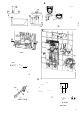
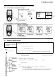
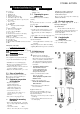
Key eo figures . [^
1 U se 'i'terfice
2 E q ub n e r:t cip
3 B a sC i b^ck v\v.l
4 I5I V V (o m p rxrsiio n ii I 'nj^
5 C ok w :iter cc'iip essio '- Itin g
6 C a:»!e gro n rrist ie lectn«.! s u p ^lv ca :> l8
fen oelo vv'
7 M?.ins ■erTriin?.!
8 lo|), •yni 'i wn I
9 E le ctron ics
10 vw 'li !-(A l i)-.vilh n n ci-xjilon
11 sysien
12 Flaw 'a te rrstf-su n n « ip F ill
13 iiocc:! i:r st:l vh u:: krtn'-diKor
14 L: D c cstic' 'tr< '.ltk lights'
15 I i> : n s^ lo^k
16 S e t V A u& •tr< ’.nsduce r c^ib e p lug
17 S afety t'S H Tia l cut o ut (S TB )
ia O ijik ^(¡•••■ ioriN IC )
19 S '<*.p-i' tsib •o r su b -r< *.ck (se vice)
20 U I H .iric |! h Ic
21 M ou n tin g o ividtje :
22 S t'v.i'e r ir. th e co ld w TO r corrio 'essio n •'fc'n?
23 lilii-c
♦
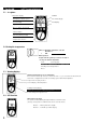
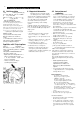
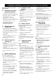
LED diiignostic ^traffic Lights''
red illurm nale s in ciise of fju lls
____
io»o VC Ho appliance Is heating water
_______
fla shin g : T he appliance Is upplicd
,reen \»i'ith powftr
___________________
General installation
information
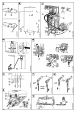
The e< ]u ipm cn c is pre p a red at the fa c *
eory fo r sta n dard in s ta lia e ion (see fig s.
» ln 5 ttf.ll*tio n a :» o vs a w orktop [C ] (a).
» W a te r cc'f.sc:ion. tn finis h e d w *l s, con
oression ftd'j? [G ] (4 *nd 5).
» E lectr'e a ' co n n e ct c '. unfi ' is 'ed w a Is. i'
t*:e low e'e q ^ip rrisrr; a'sa E l6).
» O irput 21 < V V -brth e D hE 1 ¿ ^1.^-1 S J.
5.2 Place of installation
hjta l the D hE ve'tca'Iy in *cco rc*nce w t'
Q C j (a ¿ b o v s or b be'cw w orkic?) in *
fx):rn rx)rv Ihc n sk ol irxK ..
5.3 Equipment preparation
for installation
• O pen t'e e q ^ip m e ir ^;
a P u l ih e fl:ip •brvva rc.
b O pen t'e 'kp d c*.v'w a ds.
c R tleast the fxin g sc'ew s.
d R tnov« th e e q u iiire 't ca i.
• K::novf: Ific Iwc-; whII Ijhs:: E •
» l’fx:S '< i lrv.vn 1)0 ’•• V H |)- n Ih )> .
b K::inovo liic whII Ijhs:: ';y |!••ll iij;
lo rw H 'xl'-
» R sn o ^e the f.>:in § to g g s E (IS ;.
5.4 5ecurin^i
bracketTn
• M a k ou: the fxing hole s rb ■ the rioun-
tng or<*.cltje : u sing th e institit’c' tenpU te
su p p lie d .
• ?i(:c ..r;: Ihf: •n o u n li' c -.vilh /
S tfx;»v> H '-:f I » A -i :)kic-, fn:>l '>u :)|)li:.:(l:
Securing the mounting
sdcd'rvi I lo l;:c ::l I"::
'::l(W rtnl v .-'h II).
5.5 Trimming the power
cable to size
Iri n l"(: Ixj'A-x:'(’«•)!(: lo xi/o in «rcorxrrtnco
v/i h J4 j.
N ote:
C ao (a ) sh o u k be use d a s < *.n < *.id 'c ■ ¡'•st!tl in g
t'e pow er ctble .
5.6 ^uipment installation
» R c.,t€ t's pow er c?.ble t'ro.,gh t*:« c a :» le
gronn e : i6 ; a'd oress th e b a ci.w all e ve.'
the t're a ced 5t.,ds o f the no u n ting b-'a -
eke :.
» Ft the eiu ip nsnt, seu .i'e the ix i'g toggle i1 S ).
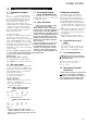
5.7 Water connection (S
l.'n p ortnt in 'biT n ;itio n:
Tho ro u gh ly flush the co ld-w atc.' su p -
ply pip e s.
A lw ays inco rpora cc th e strainer and fiu ir\g
su p p lie d (22 an d 23. bag on the co lcl*w ace r
fitting) into die col-J-water' compression fit
ting. Wfien nepl:icingt!ie insttllnion,c!ieck
ciiat the strainer' is in place.
M ove.' u se the: ch roo-w ay sh u c-o ff valve (5 )
CO reduce ebe: flow rate:.
5.8 Electrical connection
Cc"&c: the e ectrkal suoply caole to the ter- ^
irinal St ip (seeWiring dbgrair
Important information:
The pro te ction level IP 25 (h o se-
¿.Lj p rooO can only b e e n sure d w ich a cor
rectly fitted cable g rom m et i6) and seal
on the ca b le bush .
C onnect th e e q u ipm ent to earth.
5.9 Completing the
installation
1. 0|:<;" ,h:.: lfirx;(;--.v>iy •>h..l-o"valv::
2. i;i ■••::f:«rk wxl f:,?^(:E(3).
(S).
5.10 Initial start-up
(oi'ily l)V A (';jxliilC(l roi'.'rHv'lor)
o F ill and ve n t chc e q u ip m ent.
P lease note: risk of running d ryl
O pen and clo se all co n necte d d raw -o ff
va lve s se ve ral tim es, until the air has
been purg e d fro m th e p ipew ork and
the equip m e n t. seeM .2 Im p o rta n t in*
form atio n ".
o Activate the safety pressure
limiter. The DHE...SL! elecuonic
comfort is supplied with the safe^
piessure limiter (AE 3) in stripped
state (press t!ie reset button).
0 P u sh se t v a lue transduce r ca b le
plu g o n to th e P CB .
Fit the equipment cap and secure
with the screw.
o S w itch o n th e m a ins p o w er.
Check the instantaneous v/ater
heater function.
e R em ove th e p roeecciv e film from
the use r in te rfa ce.
E q uipm ent handover
E xp d n t'fe e c^ipm ent fij'ctb ' to th e ^se r
¡m e •a m i ia 'ise th e u ser w t' its oper< ttion.
Im po rtant in fo m tatio n :
• M a'< e th e ^se r avvare cf possib e c< tn g e rs
(sca ld ng).
» H *nd eve 'these inm r'u ctio n s to the use r
for sa fe keep ing.
on
7}