
Instructions / Assembly


www.stiebel-eltron-usa.com Accelera® 220-300 E | 25
ENGLISH
INSTALLATION
Installation
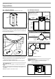
Upper DIP switch to
upper position
Lower DIP switch to
lowest position
11.4 Power supply
WARNING Electrocution
Carry out all electrical connection and installation work
in accordance with national and regional regulations.
WARNING Electrocution
If the appliance is permanently connected to the power
supply, ensure that the appliance can be separated
from the power supply by an isolator that disconnects
double terminal with at least
1
/8
˝
(4 mm) contact gap.
Contactors, disconnect switches or circuit breakers can
be used for this.
WARNING Electrocution
f Observe the safety regulations to prevent contact
with dangerous 'live' parts.
WARNING Electrocution
Coming into contact with 'live' components presents a
threat to life. Disconnect the appliance from the power
supply before carrying out work on the control panel.
Prevent the power supply from being switched on
while you are working on the system.
WARNING Electrocution
Insufficient grounding can lead to electrocution. Ensure
the appliance is grounded according to locally applica-
ble requirements.
WARNING Electrocution
The power cable must only be replaced (for example
if damaged) with an original spare part by a qualified
contractor authorized by the manufacturer. For an orig-
inal spare part contact Stiebel Eltron 800.582.8423 for
part number 315650.
!
Material losses
The voltage to the appliance must match the voltage spec-
ified on the type plate.
!
Material losses
Never connect the appliance to the power supply before
the DHW tank is filled.
11.4.1 Standard connection without external signal transmitter
The standard connection configuration for this appliance utilizes
two load connections on terminals X0/L & X0/N with a ground
connection on X0/PE. This connection requires 1 - 15 Amp dou-
ble-pole Type C breaker.
In this configuration, the appliance operates to satisfy the primary
setpoint.
BK 1
BK 2
GRN
11.4.2 Connection with off-peak power connection
The appliance can be connected to a separate 240 V connection
for a potential off-peak power source configuration. To connect
this setup, two additional load connections must be wired to ter-
minals X0/2 & X0/1. The bridges between terminals X0/N & X0/2
and between X0/L & X0/1 must be removed.
The connection on terminals X0/N & X0/L is the main connection
for operation. The installer can set up to be interrupted by ex-
ternal means for use with a timer or off-peak operational setup.
The second load connection at terminals X0/2 & X0/1 serves only
to maintain corrosion protection via the electronically impressed
anode during power interruption of the primary connection.
GND
L
L
GRN
BK 1
BK 2
L
L
Interruptible
power supply