
Instructions / Assembly


OPERATION
Settings
www.stiebel-eltron-usa.com Accelera® 220-300 E | 13
ENGLISH
4.6 Minimum runtime and minimum pause time
!
Material losses
When operating with external switching devices that can
interrupt the power supply to the appliance, such as time
switches, energy management systems or home automa-
tion systems, must adhere to the following conditions:
- The minimum ON time is 60 minutes.
- The minimum pause time following a shutdown is
20 minutes.
- The appliance should not be switched on/off more
than 10 times per day.
- The breaking capacity of the switching actuator
must meet the circuit breaker protection require-
ments (see chapter "Specification / Data table").
5. Settings
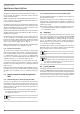
5.1 Display and controls
electronic comfort
1
3
6
7
4
13
8
11
26_03_13_0006_
c
comfor
t
4
om
for
t
4
4
5
2
10
9
14
12
1 Actual temperature
2 Set temperature 1
3 Set temperature 2 active
4 Plus key
5 Minus key
6 Service/error symbol
7 Defrost mode
8 Heat pump
9 Electric booster element
10 Freeze protection
11 Rapid heating key
12 Amount of mixed water display (l
@
40 °C /gal
@
104 °F)
Actual temperature display, upper tank section/
Set temperature1display
Set temperature2display
Fault code display
13 Menu key
14 Amount of mixed water
5.1.1 Symbols
Symbol Description
Amount of mixed water: The currently available amount of mixed
water at 104 °F (40 °C) and at 59 °F (15 °C) cold water temperature
is shown.
Actual temperature: The current actual temperature is shown. The
actual temperature indicates the temperature in the upper section
of the DHW cylinder and therefore largely corresponds to the outlet
temperature.
Set temperature 1
Set temperature2 (External signal transmitter): is the DHW set
temperature that the appliance heats to if an external signal trans-
mitter is connected and active.
Standby: The symbol flashes if the appliance PCB and load (com-
pressor) are separately supplied with power. This connection
option is required if the appliance is to be operated via switchable
sockets in an energy management system (See 11.4, “Power sup-
ply”, pg. 25) for example.
Electric booster element: This symbol indicates the presence of a
demand on this component. This symbol being displayed does not
necessarily mean that the electric booster element is in operation.
Heat pump: This symbol indicates the presence of a demand on
this component. This symbol being displayed does not necessarily
mean that the compressor is running.
Defrost mode active
Service/error: If the “service/error” symbol appears on the dis-
play, inform your qualified contractor. Continuous illumination
of the symbol indicates that the fault is not preventing appliance
operation. A flashing "Service/error" symbol indicates that water
is not being heated and that it is essential you notify your qualified
contractor. Switching the appliance to emergency mode is a special
case. The electric emergency/booster heater will then heat the
water despite the flashing "service/error" symbol.
The "electric booster element" and “heat pump” symbols are dis-
played when these appliance components are running.
Note
The back-light of the display will illuminate for 15 seconds
after pressing any button.
Service/fault symbol
Note
Notify your installer if the service/fault symbol appears
on the display. Continuous illumination of the symbol
indicates that the fault is not preventing appliance op-
eration.
A flashing service/fault symbol indicates that the water
is not being heated and that it is essential you notify
your contractor.