INSTALLATION INSTRUCTIONS AND PARTS LIST (S) DSGG-IOM-1 J30-08511 TUBULAR GAS FIRED DIRECT SPARK PROPELLER UNIT HEATERS – FOR RESIDENTIAL INSTALLATIONS – ATTENTION: READ THIS MANUAL AND ALL LABELS ATTACHED TO THE UNIT CAREFULLY BEFORE ATTEMPTING TO INSTALL, OPERATE OR SERVICE THESE UNITS! CHECK UNIT DATA PLATE FOR TYPE OF GAS AND ELECTRICAL SPECIFICATIONS AND MAKE CERTAIN THAT THESEAGREE WITH THOSE AT THE POINT OF INSTALLATION. RECORD THE UNIT MODEL AND SERIAL No.(s) IN THE SPACE PROVIDED.
TABLE OF CONTENTS SPECIFICATIONS Basic Description .................................................... 2 Performance & Specification Data ...................... 4, 5 GENERAL SAFETY INFORMATION Installation Codes ............................................... 2, 3 Special Precautions ............................................ 2, 3 INSTALLATION Locating Units ..................................................... 6, 7 Combustion Air ...................................................
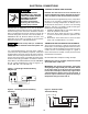
GENERAL SAFETY INFORMATION Failure to comply with the general safety information may result in extensive property damage, severe personal injury, or death. Make certain that the power source conforms to the electrical requirements of the heater. Do not depend upon a thermostat or other switch as sole means of disconnecting power when installing or servicing heater. Always disconnect power at main circuit breaker as described above. Failure to do so could result in fatal electric shock.
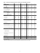
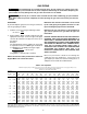
Table 1 - Performance and Dimensional Data - Tubular 30 thru 120 Propeller Unit Heater Unit Size PERFORMANCE DATA† Input - BTU/Hr. (kW) Output - BTU/Hr. (kW) Thermal Efficiency (%) Free Air Delivery - CFM (cu. m/s) Air Temperature Rise - Deg. F (Deg. C) Full Load Amps at 120V Maximum Circuit Ampacity MOTOR DATA: Motor HP Motor (kW) Motor Type R.P.M.
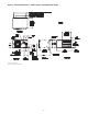
Figure 2 - Dimensional Drawing – Tubular 30 thru 120 Propeller Unit Heater DIMENSIONS .
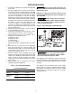
INSTALLATION Do not install unit heaters in corrosive or flammable atmospheres! Premature failure of, or severe damage to the unit will result! AIR FOR COMBUSTION: The unit heater shall be installed in a location in which the facilities for ventilation permit satisfactory combustion of gas, proper venting, and the maintenance of ambient air at safe limits under normal conditions of use.
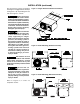
INSTALLATION (continued) The Unit Heater may be mounted by fastening the hanging brackets directly to ceiling joists or by suspending from four rods. See Figures 3, 4 and 5. Figure 3 - Hanger Bracket Installation Instructions Make certain that the lifting methods used to lift the heater and the method of suspension used in the field installation of the heater are capable of uniformly supporting the weight of the heater at all times.
GAS PIPING To avoid damage or possible personal injury, do not connect gas piping to this unit until a supply line pressure/leak test has been completed. Connecting the unit before completing the pressure/leak test may damage the unit gas valve and result in a fire hazard. Do not rely on a shut-off valve to isolate the unit while conducting gas pressure/leak tests. These valves may not be completely shut off, exposing the gas valve to excessive pressure and damage.
PIPE INSTALLATION 1. Install the gas piping in accordance with applicable local codes. 2. Check gas supply pressure. Each unit heater must be connected to a gas supply capable of supplying its full rated capacity as specified in Table 3. A field LP tank regulator must be used to limit the supply pressure to a maximum of 14 in. W.C. (3.5 kPa). All piping should be sized in accordance with the latest edition of ANSI Standard Z223.1 National Fuel Gas Code; in Canada, according to CGA-B149.
ELECTRICAL CONNECTIONS THERMOSTAT WIRING AND LOCATION: NOTICE: The thermostat must be mounted on a vertical, vibration-free surface, free from air currents, and in accordance with the furnished instructions. HAZARDOUS VOLTAGE! DISCONNECT ALL ELECTRIC POWER INCLUDING REMOTE DISCONNECTS BEFORE SERVICING. Failure to disconnect power before servicing can cause severe personal injury or death. Standard units are shipped for use on 115 volt, 60 hertz, single phase electric power.
ELECTRICAL CONNECTIONS (continued) Figure 10A - UT Control Board Figure 11A - Honeywell Control Board 11
ELECTRICAL CONNECTIONS (continued) Figure 10B - Tubular Propeller Units 30-120 with Natural and Propane (LP) Gas with Single Stage Gas Control and UT Control Board NOTICE: See Figures 7, 8, 9, 10B, 10C, 11B and 11C for connecting the thermostat to the unit heater. If using a standard low voltage thermostat with a sub-base switch for fan control, connect the G terminal of the thermostat to the G terminal of the unit heater.
ELECTRICAL CONNECTIONS (continued) Figure 10C - Tubular Propeller Units 60-120 with Natural and Propane (LP) Gas with Optional Two Stage Gas Control and UT Control Board NOTICE: See Figures 7, 8, 9, 10B, 10C, 11B and 11C for connecting the thermostat to the unit heater. If using a standard low voltage thermostat with a sub-base switch for fan control, connect the G terminal of the thermostat to the G terminal of the unit heater.
ELECTRICAL CONNECTIONS (continued) Figure 11B - Tubular Propeller Units 30-120 with Natural and Propane (LP) Gas with Single Stage Gas Control and Honeywell Control Board NOTICE: See Figures 7, 8, 9, 10B, 10C, 11B and 11C for connecting the thermostat to the unit heater. If using a standard low voltage thermostat with a sub-base switch for fan control, connect the G terminal of the thermostat to the G terminal of the unit heater.
ELECTRICAL CONNECTIONS (continued) Figure 11C - Tubular Propeller Units 30-120 with Natural and Propane (LP) Gas with Optional Two Stage Gas Control and Honeywell Control Board NOTICE: See Figures 7, 8, 9, 10B, 10C, 11B and 11C for connecting the thermostat to the unit heater. If using a standard low voltage thermostat with a sub-base switch for fan control, connect the G terminal of the thermostat to the G terminal of the unit heater.
VENTING* All unit heaters must be vented! All Venting installations shall be in accordance with the latest edition of Part 7, Venting of Equipment of the National Fuel Gas Code, ANSI Z223.1, or applicable provisions of local building codes. Refer to notes* below for Canadian installations. Refer to Figures 12-19. CARBON MONOXIDE! Your venting system must not be blocked by any snow, snow drifts, or any foreign matter.
VENTING - GENERAL GUIDELINES ANSI now organizes vented appliances into four categories. The following guidelines apply to all categories to follow. Venting Categories Table 4 Vent Systems Termination Clearance Requirements Structure Negative Vent Pressure Positive Vent Pressure Minimum Clearances for Termination Locations 4 feet below Door, window or any gravity vent inlet 4 feet horizontally Non Condensing Condensing I II III IV 1 foot above Forced air inlet within 10 ft.
STANDARD COMBUSTION VERTICALLY VENTED, CATEGORY I - Figure 12 Observe the following precautions when venting the unit: 1. Use flue pipe of the same size as the flue connection(s) on the gas unit heater 4" (102mm). All heaters must be vented with a UL Listed, Type B or single wall vent, a factory built chimney, or a lined brick and mortar chimney that has been constructed in accordance with the National Building Code.
Table 5 - Category I Horizontal Venting Requirements - Standard Combustion Vent Diameter (in) Maximum Number Elbows * Maximum Horizontal Vent Length (Ft.) Minimum Vertical Rise (In.) Extension Distance from Wall (In.) 30 4 4 1 2 5 10 8 18 36 36 45 4 4 4 1 1 2 10 15 5 24 24 24 36 36 36 60 4 2 10 18 36 75 5 2 7 24 36 90 5 2 7 24 24 105 5 2 7 24 24 120 5 1 5 24 24 5 2 7 24 24 Unit Size *One elbow is required to make the vertical extension, See Figure 13.
Figure 14 - Vent Support D- 06839A 20
STANDARD COMBUSTION HORIZONTALLY VENTED, CATEGORY III - Figure 15 Vent Systems Termination Clearance Requirements Structure Minimum Clearances for Termination Locations 4 feet below Door, window or any gravity air inlet 4 feet horizontally 1 foot above Forced air inlet within 10 ft. 3 feet above Adjoining building or parapet 6 feet Adjacent public walkways 7 feet above grade Observe the following precautions when venting the unit: 1.
STANDARD COMBUSTION VERTICALLY VENTED, CATEGORY III – Figure 17 & 19 Observe the following precautions when venting the unit: 1. Use flue pipe of the same size as the flue connection(s) on the gas unit heater, 4" (102mm). All heaters must be vented with a single or double wall pipe listed for positive pressure vent systems. 2. Each unit must have an individual vent pipe and vent terminal. Unit MUST NOT be connected to other vent systems or to a chimney. 3.
Figure 15A - Category III Horizontal Venting Requirements Using Single Wall Vent Pipe Figure 15B - Category III Horizontal Venting Requirements Using Type B Double Wall Vent Pipe Figure 15C - Type B Draft Hood Connector 23
VENTING (continued) Figure 16 Figure 17 24
VENTING (continued) Figure 18 Figure 19 25
SEPARARTED COMBUSTION INSTALLATION - VENTING – CATEGORY III COMBUSTION AIR VENTING AND PIPING 5. Long runs of single wall combustion air piping passing through an unheated space may require insulating if condensation becomes noticeable. 6. The combustion air system must be installed to prevent collection of condensate. Pitch horizontal pipes downward 1/4 inch per foot toward the inlet cap to facilitate drainage. Vertical combustion air pipes should be piped as depicted in Figure 22. 7.
SEPARATED COMBUSTION VENTING (continued) 4. Use single wall pipe constructed of 26 GA galvanized NOTICE: Increasing the clearance distances may steel or a material of equivalent durability and corrosion be necessary if there is a possibility of distortion or resistance for the vent system. For installations in discoloration of adjacent materials. Canada, use corrosion resistant and gas-tight, listed vent pipe conforming with local building codes, or 11.
Figure 21 - Concentric Vent Installation Figure 22 - Vertical Intake/Vent Installation 28
VENTING (continued) Figure 23 - Horizontal Intake/Vent Installation Figure 24 - Horizontal Intake/Vent Installation Building Overhang 3'-0" Min. (0.9M Min.) Adjacent Building 6'-0" Min. (1.8M Min.
SEPARATED COMBUSTION VENTING (continued) HORIZONTAL TERMINATION Select a location on outside wall for vent terminal. In most applications, the terminal should be on level with the flue outlet of the unit less a 1/4 inch per foot pitch for condensate drainage toward the outside of the building. See Figure 23. AIR INLET COLLAR Remove screen and mounting plate from air inlet on rear panel of unit by removing 4 screws. Secure inlet collar and gasket to inlet opening re-using the 4 screws removed in step one.
OPERATION POWER VENTED PROPELLER UNITS DIRECT SPARK IGNITION EXPLANATION OF CONTROLS (See Figure 25): 1. Each Unit Heater comes equipped with a power vent system that consists of a power venter motor and blower, pressure switch, and sealed flue collector in place of the conventional draft diverter. 2. The power venter motor is energized by the room thermostat through the integrated control board when a demand for heat is sensed.
PRIMARY AIR SHUTTER ADJUSTMENT Primary air adjustment is made at the factory. No field adjustments are necessary. GAS INPUT RATE Check the gas input rate as follows (Refer to General Safety Information section for metric conversions). 2. PROPANE GAS: An exact manifold pressure of 10.0 inches W.C. (2.5 kPa) must be maintained for proper operation of the unit heater. If the unit is equipped with a pressure regulator on the combination gas valve, follow steps "a" through "d" above.
Table 8 NATURAL GAS Altitude (Feet) 2,000 2,500 3,000 3,500 4,000 4,500 5,000 5,500 6,000 *Heating Value BTU/Cu. ft. 948 931 914 897 881 865 849 833 818 Manifold Pressure (In. W.C.) 3.5 3.5 3.5 3.4 3.4 3.4 3.3 3.3 3.2 PROPANE (LP) GAS *Heating Value BTU/Cu. ft. 2,278 2,237 2,196 2,156 2,116 2,077 2,039 2,000 1,964 NATURAL GAS Manifold Pressure (In. W.C.) Altitude (Feet) 6,500 7,000 7,500 8,000 8,500 9,000 9,500 10,000 10.0 10.0 10.0 10.0 10.0 9.9 9.7 9.6 9.5 *Heating Value BTU/Cu. ft.
Table 9 - Tubular Propeller Troubleshooting Guide SYMPTOMS POSSIBLE CAUSE(S) CORRECTIVE ACTION A. Flame pops back. 1. Burner orifice incorrect. 2. Low manifold Pressure. 1. Check for proper orifice size. Refer to “Operation”. 2. Test and reset manifold pressure. B. Noisy Flame. 1. Irregular orifice causing whistle or resonance. 2. Excessive gas input. 1. Replace orifice. 2. Test and reset manifold pressure. C. Yellow tip flame (some yellow tipping on LP gas is permissible). 1. Clogged burner. 2.
Table 9 - Tubular Propeller Troubleshooting Guide (continued) SYMPTOMS I. Burner will not shut off. POSSIBLE CAUSE(S) 1. Thermostat located incorrectly. CORRECTIVE ACTION 5. Excessive gas supply pressure. 1. Relocate thermostat away from outside wall or drafts. 2. Check thermostat circuit for open and close on terminal strip on heater “R” and “W”. 3. Check thermostat circuit for shorts “staples piercing wires”. 4. Check for 24v on gas valve terminals when thermostat is not calling. 5.
Table 9 - Tubular Propeller Troubleshooting Guide SYMPTOMS POSSIBLE CAUSE(S) CORRECTIVE ACTION R. Cold air is delivered during heater operation. 1. Incorrect manifold pressure or input. 1. Refer to “Operation”. S. High limit tripping. 1. Unit is over fired. 1. Burner orifice may be too large, verify and replace. 2. Check for proper voltage, ensure fan blade is correctly positioned 1/3 inside venturi. 3.
Table 10A - Troubleshooting with LED Indicator Assistance for UT Control Board INDICATES LED STATUS Line voltage power can cause product damage, severe injury or death. Only a trained experienced service technician should perform this troubleshooting. 1. Check the system thermostat to make sure it is calling for heat. (Do not cycle the thermostat on and off at this time.) 2. Remove the access panel. Do not interrupt power to the control board by opening any electrically interlocked panels. 3.
Table 10B - Troubleshooting with LED Indicator Assistance for Honeywell Control Board STATUS PATTERN CHECK/REPAIR Short Flash Control powered (without call for Heat) Not Applicable Heartbeat Call for Heat: normal operations Not Applicable 2 Pressure Switch failed closed 1. Check pressure switch to see if open to start, if not replace switch. 2. Air flow switch jumpered. Remove jumper and check operation. 3 Pressure Switch failed open 1.
IDENTIFICATION OF PARTS RESIDENTIAL TUBULAR 30-120 MBH UNIT SIZES Item No.
IDENTIFICATION OF PARTS RESIDENTIAL TUBULAR 30-120 MBH UNIT SIZES Figure 26 - Propeller Parts Figure 27 - Component Parts Fan Blade Fan Guard Motor Hardware D03339 D03339 Hardware Pressure Switch D4430 NOTE: No rubber grommets are supplied with the 30 and 45 unit sizes.
HOW TO ORDER REPLACEMENT PARTS Please send the following information to your local representative: if further assistance is needed, contact the manufacturer's customer service department. •Model Number •Serial Number •Part Description and Number as shown in Replacement parts Catalog LIMITED WARRANTY Residential Power Vented Tubular Propeller Unit Heaters 1.
Low Profile Tubular Gas-Fired Unit Heater Model Number Description Digit G X Item X X — 1 Prefix 2 UT 3 4 5 CA 6 7 8 9 10 11 12 13 14 15 + FT FM GT AL GC SV MT DL AS (Internal use Only) 1, 2 - Unit Type [UT] 11 - Supply Voltage [SV] GG - Residential Tubular Propeller UH 1 - 115/1/60 4 - 208/3/60 7 - 575/3/60 2 - 208/1/60 5 - 230/3/60 Z - Other 3 - 230/1/60 6 - 460/3/60 Note: Supply Voltage [SV] 2 thru 7 includes a field mounted step down transformer.
GAS EQUIPMENT START-UP Customer ____________________________________ Job Name & Number _________________________ PRE-INSPECTION INFORMATION With power and gas off. Unit Heater Type of Equip: Serial Number _________________________ Model Number __________________________ Name Plate Voltage: _____________ Name Plate Amperage: _____________ Type of Gas: Natural Tank Capacity _______ lbs.
HVAC PRODUCTS 260 NORTH ELM ST., WESTFIELD, MA 01085 TEL: (413) 564-5540 FAX: (413) 562-5311 www.sterlinghvac.