
RSD Series Installation Guide


Form #43219040
Jan 2014
OUTLET GAS PRESSURE CHECK AND ADJUSTMENTS (WHITE-RODGERS 1 STAGE) GAS VALVES
Gauges that measure pressure in pounds per square inch are not accurate enough to measure or set the manifold
pressure. All measurements MUST BE made when the heater and all other gas burning equipment that is
connectied to the gas supply system are operating at maximum capacity. The combination gas valve is factory set
and should not need adjustment. If gas pressure adjustment is required, follow the instructions:
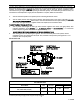
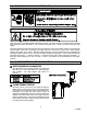
1. Turn off all electrical power to the system prior to connecting manometer hoses.
2. Turn the outlet pressure boss test screw (3/32” Hex allen wrench plug) in the center of the boss not more
than one turn counterclockwise. Attach a 5/16” hose and manometer over the tapered outlet pressure boss
on the valve (see figure below). If regulator needs to be adjusted, see instructions below.
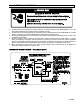
To Adjust Regulator (1-stage gas valves):
1. Turn on power and energize the main gas valve. Remove regulator cover screw (see figure below). Turn
regulator adjustment screw clockwise to increase presure, or counterclockwise to decrease
pressure. Replace regulator cover screw and tighten securely.
DO NOT EXCEED THE PRESSURES SHOWN IN THE GAS PRESSURE TABLE.
2. After testing pressure and adjusting the regulator, turn off all electrical power to the system, remove
manometer hoses, turn outlet test screw (3/32” Hex) clockwise to seal pressure port. Tighten to 7 in lb
minimum. Turn on system power.
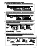
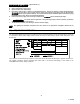
Model Suffix 1D
GAS PRESSURE TABLE
HEATER MODEL
GAS
TYPE
MANIFOLD
PRESSURE
SUPPLY PRESSURE
Minimum
Maximum
R (B,S,M) D (030, 035, 040, 060, 070, 080, 100
120, 140 & 160) N1 (C,D)
Natural
6” W.C.
7” W.C.
14” W.C.
R (B,S,M) D (033, 066, 100 & 132) L1 (C,D)
Propane
10” W.C.
11” W.C.
14” W.C.
Minimum permissible gas supply pressure for purpose of input adjustment.
11