GP Series Portable Chillers Part Number: 882.93092.00 Bulletin Number: SC2-620.2 Effective: 1/12/2010 Write Down Your Serial Numbers Here For Future Reference: _________________________ _________________________ _________________________ _________________________ _________________________ _________________________ We are committed to a continuing program of product improvement. Specifications, appearance, and dimensions described in this manual are subject to change without notice. ECN No.
Shipping Information Unpacking and Inspection You should inspect your equipment for possible shipping damage. Thoroughly check the equipment for any damage that might have occurred in transit, such as broken or loose wiring and components, loose hardware and mounting screws, etc. In the Event of Shipping Damage According to the contract terms and conditions of the Carrier, the responsibility of the Shipper ends at the time and place of shipment.
Table of Contents CHAPTER 1: SAFETY................................................................ 5 1-1 1-2 1-3 How to Use This Manual ............................................................................................. 5 Safety Symbols Used in this Manual .....................................................................5 Warnings and Precautions .......................................................................................... 6 Responsibility .......................................
-1 4-2 4-3 4-4 4-5 4-6 4-7 Panel Buttons, Indicator Lights, and Switches .......................................................... 29 Microprocessor Controller ...................................................................................29 Initial Start-up ............................................................................................................ 30 Status Screens ..........................................................................................................
Chapter 1: 1-1 Safety How to Use This Manual Use this manual as a guide and reference for installing, operating, and maintaining your equipment. The purpose is to assist you in applying efficient, proven techniques that enhance equipment productivity. This manual covers only light corrective maintenance. No other maintenance should be undertaken without first contacting a service engineer. The Functional Description section outlines models covered, standard features, and optional features.
1-2 Warnings and Precautions Our equipment is designed to provide safe and reliable operation when installed and operated within design specifications, following national and local safety codes. To avoid possible personal injury or equipment damage when installing, operating, or maintaining this equipment, use good judgment and follow these safe practices: 9 Follow all SAFETY CODES. 9 Wear SAFETY GLASSES and WORK GLOVES. 9 Disconnect and/or lock out power before servicing or maintaining the equipment.
Chapter 2: 2-1 Functional Description Models Covered in This Manual This manual provides operation, installation, and maintenance instructions for air-, water-and remote air-cooled portable chillers. Model numbers are listed on the serial tag. Make sure you know the model and serial number of your equipment before contacting the manufacturer for parts or service.
The refrigerant is compressed in the compressor and flows through the discharge line as a gas to the condenser. There it gives up its heat as it condenses to a liquid in the condenser. An electronic hot gas bypass valve is used to control cooling capacity during intermittent or partial load conditions. This feature contributes substantially to chiller longevity by eliminating excessive cycling of the compressor and providing close temperature control. 2-3 Standard Features Mechanical Features Compressor.
• 208-230/3/60, 460/3/60, 575/3/60 volt; 400/3/50 volt Refrigeration Features • HFC-410a refrigerant • Electronic hot gas bypass capacity control • High refrigerant pressure cutout switches • Suction and discharge pressure transducers.
Caution! Energize the crankcase heater for at least 24 hours before initial startup to drive dissolved refrigerant from the compressor oil. Failure to do so will damage the compressor. High Pressure Cutout This electro-mechanical cutout device opens the compressor control circuit if the refrigeration system compressor discharge pressure exceeds 575 psi.. Note: The high-pressure cutout is a manual reset device typically mounted on the compressor discharge line inside the mechanical cabinet.
Process Water Side-stream Filter*. Not available on chillers less pump and reservoir tank. This option includes a 50 micron filter, flow meter, ball valve for throttling water flow, and the necessary piping to provide constant filtering of the process water at about one gallon per minute (1 gpm/3.8lpm). General Fault Indicator Audible/Visual Alarm*. This option includes a 100 dB audible alarm horn/ visual alarm strobe and silence button with provisions for customer wiring indication interlock.
Figure 1: Optional Pump Amperages Voltage Construction HP 460/3/60 SS 1 1.7 1.5 2.3 2 4.0 3 4.2 5 8.2 GP Series Portable Chillers Full Load Amps 7.5 10.3 10 12.0 15 20.0 30 32.
Chapter 3: 3-1 Installation Uncrating All models are shipped mounted on a skid, enclosed in a plastic wrapper, and open-crated on all four sides and top. 1. Pry the crating away from the skid. 2. Use a pry bar to remove the blocks securing the unit to the skid. 3. Lift unit from sides, inserting forklift under the base. The forks must be equidistant from the centerline of the unit and the unit must be balanced on the forks. Lift slowly and only high enough to clear the skid.
3-3 Process Water Connections All of our portable chillers have two chilled water connections. The chilled water supply, labeled “To Process” is the outlet for the chilled water leading to the process being cooled. The chilled water return, labeled “From Process” is the inlet leading from the process back into the chiller to be cooled and re-circulated. All external chilled water connections should be run full size to the process. Flow and pressure information is available in the Appendix.
3-7 Condenser Considerations Water-Cooled Chiller Condensers Water-cooled portable chillers can use city water or tower water as a cooling medium. Make sure that all external piping and connections supplying and discharging water to and from the condenser are full size. You will make two connections to the water-cooled condenser: Condenser Water In. The condenser water supply, labeled “Condenser Water In”, is located at the rear of the chiller. It is the inlet for city or tower water.
installation. If there is no pressure, leak test the unit and repair before installing the interconnecting refrigerant piping. Read this entire section before installation. Note: Piping should be type “L” or type “K” refrigerant grade copper tubing only. Proper sizing and installation has a significant effect on system performance, reliability, and safety. Interconnecting Refrigerant Piping. The chiller and condenser refrigerant lines are terminated with a cap and brazed closed.
room. Install a liquid line-charging valve to facilitate refrigerant charging. See Figure 3 on page 18 for sizing information. See Figure 5 on page 22 for charge determination. Discharge Line Sizing. For horizontal runs, the discharge line should be pitched downward, in the direction of flow, at a rate of 1/2” for every 10 feet. This will allow oil to flow towards the condenser. Discharge line sizing is based on the velocity required for sufficient oil return back to the compressor.
Figure 4 on page 21 for discharge line sizing. Figure 2: Equivalent Length in Feet for Valves and Fittings Line Size OD (inches) 3/8 1/2 5/8 3/4 7/8 1-1/8 1-3/8 1-5/8 2-1/8 2-5/8 Angle Valve 24 24 25 25 28 29 33 34 39 44 Short Radius EL 4 4.7 5.7 6.5 7.8 2.7 3.2 3.8 5.2 6.5 Long Radius EL 2.8 3.2 3.9 4.5 5.3 1.9 2.2 2.6 3.4 4.2 Figure 3: Liquid Line Sizing 5 TON CIRCUIT 7.5 TON CIRCUIT Liquid Line Size (OD") Liquid Line Size (OD") Total Equiv.
10 TON CIRCUIT 15 TON CIRCUIT Liquid Line Size (OD") Total Equiv. Length (Ft) 25 50 75 100 125 150 175 200 225 250 275 300 Liquid Line Size (OD") Horizontal or Downflow Upflow 1-5 Ft Upflow 6-10 Ft Upflow 11-15 Ft 5/8 5/8 5/8 5/8 3/4 3/4 3/4 3/4 3/4 3/4 3/4 3/4 5/8 5/8 5/8 3/4 3/4 3/4 3/4 3/4 3/4 3/4 3/4 3/4 5/8 3/4 3/4 3/4 3/4 3/4 3/4 3/4 7/8 7/8 7/8 7/8 3/4 3/4 3/4 3/4 7/8 7/8 7/8 7/8 7/8 7/8 7/8 7/8 20 TON CIRCUIT Total Equiv.
30 TON CIRCUIT 40 TON CIRCUIT Liquid Line Size (OD") Liquid Line Size (OD") Total Equiv. Length (Ft) Horizontal or Downflow Total Equiv.
Figure 4: Discharge Line Sizing Horizontal or Downflow Discharge Line Sizes (OD") Total Equivalent Length (Ft) Circuit Tons 25 50 75 100 125 150 175 200 225 250 275 300 5 5/8 5/8 5/8 5/8 3/4 3/4 3/4 3/4 3/4 3/4 3/4 7/8 7.
Refrigerant Charge Determination. The approximate amount of refrigerant charge required by the system varies based on the total length of the refrigerant lines and the size of the chiller. Referring to Figure 5, determine the amount of charge based on the horsepower of the chiller and the amount of charge based on discharge and liquid line sizes and lengths. Add these three numbers together to find the final operating charge.
3-8 Checking Motor Direction All of our portable chillers have their motor rotations properly phased at the factory. If compressors, pumps, or fans are running in reverse rotation, disconnect and lock out the power source and reverse any two power leads into the chiller disconnect switch. Caution! Do not switch leads at the motors, motor starters, or contactors. Three-Phase Compressors Scroll compressors are directionally-dependent and compress in one rotational direction.
3-9 Water Reservoir All portable chillers shipped during the fall, winter, or spring, or those units that are shipped from stock are flushed at the factory with a water/ethylene glycol solution to prevent piping components prone to retaining water from freezing.
Figure 6: Ethylene Glycol and Propylene Glycol Curves Pe rce n t G lyc o l Cu rves fo r F ree ze P ro tec tion 40.0 30.0 Eth ylene G lycol 20.0 P rop ylene G lyc ol 10.0 0.0 -10.0 -20.0 -30.0 -40.0 -50.0 -60.0 0.0 10.0 20.0 30.0 40.0 50.0 60.0 % Gl ycol by Vol um e Example: 45°F set point minus 20°F = 25°F. From Figure 28, 25°F equates to 10% by volume of glycol required.
3-10 Automatic Water Make-Up Option The chiller may be connected to an automatic make-up system if the optional package (pipe fittings, solenoid valve and 1/2” NPT city water make-up connection) is factory installed. If the automatic make-up system is connected to a city water system, make provisions to prevent backflow contamination. Install an approved backflow preventer in accordance with local codes.
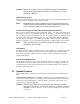
Operator Password. If you define a password for operators, then a password will be required to carry out any function (other than reviewing the status screens). Entering the operator’s password will give the user access to the setpoints for leaving temperature, high temperature warning, high temperature fault. Supervisor Password. If you define a password for supervisors (or setup personnel) then most settings can be changed only after entering the password.
6. Press to accept the Password and move to the next line. 7. For either Operator or Supervisor password the time that the password will allow the controller to be active can be set by the Operator or Supervisor Password Time. With the or to increment or decrement the time. The PW Time value highlighted, press password time for either setup can be from 0 to 99 minutes.
Chapter 4: 4-1 Operation Panel Buttons, Indicator Lights, and Switches Microprocessor Controller The standard chillers use a microprocessor-based PID controller. The Carel PCO controller along with the Carel PGD1 Interface is a modular, self-contained unit that can slide from its mounting housing. It is factory set and adjusted; no field adjustment to the internal controls is necessary. The standard operation range is 20ºF to 80ºF (-7ºC to 27ºC).
4-2 Initial Start-up 1. Verify the initial start-up checklist from Chapter 3, Section 3-11. 2. With the main supply power switch in the ON position, the screen will display the version of the software for a period of 5 seconds, and then display the main status screen. Figure 8 - Main Status Screen 3. Set the Leaving Fluid temperature by depressing the the menu. button to display Figure 9 - Menu Screen or button to highlight SETPOINTS and press . If 4.
appear. Figure 10 - Operator Setpoints Screen to move the cursor to the Leaving Temp line. Use the 5. Depress button to increment or decrement the value. Depress value and move the cursor down one line. 6. Depress the or to accept the button twice to return to the main status screen. to start the chiller. 7. Depress the 8. Check pump rotation 9. Check the pump amp draw and pump pressure. Make sure that the amp draw reading is within the running load and service factor amps. 10.
outputs for the controller. The Test aides in troubleshooting the chiller when it is not functioning properly by displaying the basic information that a service person will need to know to determine the problem.
4-4 Access Levels The controller is setup to allow access to three distinct password groups: operator, supervisor, and service. Operator access allows the user to modify the Leaving Water Temp, Hi Temp Warning, and Hi Temp Fault setpoints. Supervisor access allows the supervisor to modify the above plus Selecting any of the menus in the Menu Screen will display the Password Screen.
4-5 Controller Setpoints Variable Leaving Temp Description Temperature of fluid out to process Low Temperature Warning Setpoint for alarm to warn when leaving fluid temperature is too high Setpoint to shut down pump and compressor based on leaving fluid temperature Temperature Difference between Leaving Fluid Temperature and Setpoint to turn on the compressor Temperature Difference between Leaving Fluid Temperature and Setpoint to turn off the compressor Delay time in seconds between fault and stopping
2. Depress the or button to highlight SETPOINTS and press . If passwords were setup (See Section 3-12 for information on the controller passwords) the password screen will appear. Enter the Operator Password by depressing the to move the position of the cursor, and then depressing the or button to increment or decrement the number. Once all of the numbers have been entered depress the to accept the password. The following screen will appear.
When using the communications function, you must add on the unit for RS-485 Modbus communications. The communications function allows you to read/write parameters, do operating instructions, and select the setting level.
GP Series Portable Chillers Chapter 4: Operation 37 of 73
Chapter 5: 5-1 Maintenance Lubrication Grease all fan motors, and pump motors that do not have permanently sealed bearings. Be sure to use an all-purpose industrial grease with a temperature reference of 185˚ F (85˚ C). Remove the grease relief plug (motors only) before adding grease, add grease until a small amount pours out, and replace the plug when finished. Caution! Failure to remove the grease relief plug will result in dislodging the bearing grease seal, eventually causing bearing failure.
Caution! Do not use steam or water over 140ºF (60ºC) to clean a condenser unless you are monitoring the refrigeration circuit for excessive pressure with gauges. Only a trained technician should use this method. 5-4 Maintaining the Evaporator Dirty evaporator heat exchange surfaces reduce system capacity and efficiency. Remove dirt and slime in the evaporator by reverse-circulating with a mild detergent and water solution.
Chapter 6: Problem Troubleshooting Possible cause No power. Wrong voltage supplied to unit. Defective display. Unit does not run. Control circuit fuse blown. Defective control transformer. Piping flow switch circuit open. Pump motor off on overload. Leaving fluid setpoint set higher than temperature of liquid in system. Compressor internal overload or fuses are open. Pump runs; compressor does not. Compressor contactor holding coil open. Defective compressor auxiliary contact.
Problem Pump process pressure low (refer to curves for normal pressure for various pumps). Possible cause Pump running in reverse. Check for foreign matter. Pump process pressure is too high. Restricted water flow. Restricted condenser air flow. Unit runs continuously, but not enough cooling power. Unit low on refrigerant. Compressor not operating efficiently. Unit under-sized for application.
Chapter 7: 7-1 Appendix Returned Material Policy Credit Returns Prior to the return of any material, authorization must be given by the manufacturer. A RMA number will be assigned for the equipment to be returned. Reason for requesting the return must be given. All returned Material purchased from the manufacturer is subject to 15% ($75.00 minimum) restocking charge. All returns are to be shipped prepaid. The invoice number and date or purchase order number and date must be supplied.
7-2 Technical Assistance Parts Department Call toll-free 7am–5pm CST [800] 423-3183 or call [262] 641-8610, Fax [262] 641-8653 The ACS Customer Service Group will provide your company with genuine OEM quality parts manufactured to engineering design specifications, which will maximize your equipment’s performance and efficiency. To assist in expediting your phone or fax order, please have the model and serial number of your unit when you contact us.
7-3 Specifications Air-Cooled Portable Chillers Nominal operating parameters for air-cooled models are 50ºF (10ºC) leaving water temperature at 2.4 gpm per ton (9.1 lpm per 3.517 kW) with 95ºF (35ºC) ambient air. For 50 Hz applications, multiply capacity by 0.83. Nominal 60 Hz capacity flow rate must be maintained. G-PAC-20 PERFORMANCE (NOMINAL DESIGN CONDITIONS) COOLING CAPACITY 4.
G-PAC-40 PERFORMANCE (NOMINAL DESIGN CONDITIONS) COOLING CAPACITY 9.91 TONS ALTITUDE SEA LEVEL COOLANT SUPPLY TEMPERATURE 50 °F COMPRESSOR POWER 10070 WATTS AMBIENT AIR TEMPERATURE 95 °F EER 11.
GPAC-70 PERFORMANCE (NOMINAL DESIGN CONDITIONS) COOLING CAPACITY 20.16 TONS ALTITUDE SEA LEVEL COOLANT SUPPLY TEMPERATURE 50 °F COMPRESSOR POWER 20048 WATTS AMBIENT AIR TEMPERATURE 95 °F EER 12.
GPAC-105 PERFORMANCE (NOMINAL DESIGN CONDITIONS) COOLING CAPACITY 30.21 TONS ALTITUDE SEA LEVEL COOLANT SUPPLY TEMPERATURE 50 °F COMPRESSOR POWER 29731 WATTS AMBIENT AIR TEMPERATURE 95 °F EER 12.
GPAC-175 PERFORMANCE (NOMINAL DESIGN CONDITIONS) COOLING CAPACITY 49.41 TONS ALTITUDE SEA LEVEL COOLANT SUPPLY TEMPERATURE 50 °F COMPRESSOR POWER 48693 WATTS AMBIENT AIR TEMPERATURE 95 °F EER 12.
Water-Cooled Portable Chillers Nominal operating parameters for water-cooled models are 50ºF (10ºC) leaving water temperature at 2.4 gpm per ton (9.1 lpm per 3.517 kW) with 85ºF (29ºC) tower water. For 50 Hz applications, multiply capacity by 0.83. Nominal 60 Hz capacity flow rate must be maintained. G-PWC-20 PERFORMANCE (NOMINAL DESIGN CONDITIONS, 60 HZ) COOLING CAPACITY COOLANT SUPPLY TEMPERATURE CONDENSER INLET WATER TEMPERATURE COOLANT COOLANT FLOW UNIT PRESSURE DROP 5.
G-PWC-40 PERFORMANCE (NOMINAL DESIGN CONDITIONS) COOLING CAPACITY COOLANT SUPPLY TEMPERATURE CONDENSER INLET WATER TEMPERATURE COOLANT COOLANT FLOW UNIT PRESSURE DROP 10.94 50 TONS °F 85 °F WATER 27 GPM 7 PSID ALTITUDE COMPRESSOR POWER 8450 SEA LEVEL WATTS EER 15.53 BTU/WATT CONDENSER WATER FLOW SOUND POWER LEVEL SOUND PRESSURE LEVEL @ 1 METER 33.
GPWC-70 PERFORMANCE (NOMINAL DESIGN CONDITIONS) COOLING CAPACITY 22.68 COOLANT SUPPLY TEMPERATURE CONDENSER INLET WATER TEMP COOLANT TONS 50 °F 85 °F WATER COOLANT FLOW ALTITUDE 16970 WATTS EER 16.
GPWC-105 PERFORMANCE (NOMINAL DESIGN CONDITIONS) COOLING CAPACITY 33.64 TONS ALTITUDE SEA LEVEL COOLANT SUPPLY TEMPERATURE 50 °F COMPRESSOR POWER 25508 WATTS CONDENSER INLET WATER TEMP 85 °F EER 15.
GPWC-175 PERFORMANCE (NOMINAL DESIGN CONDITIONS) COOLING CAPACITY 54.46 TONS ALTITUDE SEA LEVEL COOLANT SUPPLY TEMPERATURE 50 °F COMPRESSOR POWER 41633 WATTS CONDENSER INLET WATER TEMP 85 °F EER 15.
7-4 Pump Curves, Flow, and Pressure Considerations 60 Hertz Pump Curves 5-15 ALL 60 Hz ACS CHILLER PUMPS September 8, 2009 300 120 250 100 10 HP 3U 32-200-1100D3G 200 80 3 HP 2CDU 70/306 150 Psi Head [ft] 5 HP 2CDU 200/506 60 2 HP CDU 70/520D3G 3 HP CDU120/530D3G 100 40 1.5 HP CDU 70/315D3G 50 20 0 0 0 10 20 30 40 50 60 70 80 Capacity [Gal/min] HP 1.
70-210 ALL 60 Hz ACS CHILLER PUMPS September 8, 2009 300 120 250 100 15 HP 3U 40-200B150D3G 200 5 HP 2CDU 200/506 10 HP 3U 32-200-1100D3G 80 Bar Head [ft] 30 HP 3UB 65-200300D3G 5 HP 3U 32-160B50D3G 150 10 HP 3U 40-160-1100D3G 60 7.5 HP 3U 40-160-75D3G 5 HP CDU200/550D3G 100 40 5 HP 3U 40-125B-50D3G 50 20 0 0 60 120 180 240 0 300 Capacity [Gal/min] HP 5 5 5 5 7.
50 Hertz Pump Curves 5-15 ALL 50 Hz ACS CHILLER PUMPS September 8, 2009 70 6 60 10 HP 3U 32-200-1100D3G 5 50 4 40 Bar Head [m] 5 HP 2CDU 200/506 3 HP 2CDU 70/306 3 30 3 HP CDU120/530D3G 2 HP CDU 70/520D3G 2 20 1.5 HP CDU 70/315D3G 1 10 0 0 0 50 100 150 200 250 300 Capacity [liter/min] HP 1.
20-50 ALL 50 Hz ACS CHILLER PUMPS September 8, 2009 70 6 60 10 HP 3U 32-200-1100D3G 5 50 4 40 Bar Head [m] 5 HP 2CDU 200/506 3 HP 2CDU 70/306 3 30 2 20 2 HP CDU 70/520D3G 3 HP CDU120/530D3G 1.5 HP CDU 70/315D3G 1 10 0 0 50 100 150 200 250 0 300 Capacity [liter/min] HP 1.
Pure Water at >40°F GPXC-20 GPXC-30 GPXC-40 GPXC-50 GPM DP (PSI) GPM DP (PSI) GPM DP (PSI) GPM DP (PSI) 0.5X Nominal 6 1.0X Nominal 12 1.7 9 1.7 12 1.6 18 1.8 5.9 18 6.1 24 5.8 36 2.0X Nominal 24 6.4 21.4 36 21.9 48 20.7 72 23.3 0.5X Nominal 24 1.7 30 1.8 36 1.7 48 1.0X Nominal 48 6.1 60 6.5 72 6.1 96 6.4 2.0X Nominal 96 21.9 120 23.5 144 22.1 192 23.6 0.5X Nominal 72 1.0X Nominal 144 6.2 2.0X Nominal 288 22.
7-5 Remote Air-Cooled Chiller Configurations GP Series Portable Chillers Chapter 7: Appendix 59 of 73
7-6 Typical Ductwork for Air-Cooled Chillers Fan Model GPAC-20 GPAC-30 GPAC-40 GPAC-50 GPAC-70 GPAC-90 GPAC-105 GPAC-140 GPAC-175 GPAC-210 HP 0.5 1.0 1.0 2.0 (2) 1.0 (2) 2.0 (2) 2.0 (3) 2.0 (3) 2.0 (4) 2.0 kW 0.4 0.7 0.7 1.5 (2) 0.7 (2) 1.4 (2) 1.4 (3) 1.4 (3) 1.4 (4) 1.
chiller • Back draft damper to outside must be closed at all times when fan/blower is not operating • Chillers with dual fans/blower must have a back draft damper on the cycling fan/blower to prevent recirculation of hot discharge air • Chillers are designed to operate at a condensing entering air temperature of 60ºF (16ºC) minimum without optional Variable Frequency Drive • Maximum total static pressure drop external to the chiller must not exceed 0.
7-7 Piping Diagrams GP Series Portable Chillers Chapter 7: Appendix 62 of 73
GP Series Portable Chillers Chapter 7: Appendix 63 of 73
GP Series Portable Chillers Chapter 7: Appendix 64 of 73
GP Series Portable Chillers Chapter 7: Appendix 65 of 73
GP Series Portable Chillers Chapter 7: Appendix 66 of 73
GP Series Portable Chillers Chapter 7: Appendix 67 of 73
GP Series Portable Chillers Chapter 7: Appendix 68 of 73
GP Series Portable Chillers Chapter 7: Appendix 69 of 73
GP Series Portable Chillers Chapter 7: Appendix 70 of 73
GP Series Portable Chillers Chapter 7: Appendix 71 of 73
GP Series Portable Chillers Chapter 7: Appendix 72 of 73
GP Series Portable Chillers Chapter 7: Appendix 73 of 73