Operation and Installation Manual 6010 Series Midsize Hot Oil Temperature Control Units Important! Read Carefully Before Attempting to Install or Operate Equipment Part No. 682.93125.00 Bulletin No.
Write down your unit serial number(s) ________________ ________________ here for future reference ________________ ________________ ________________ ________________ ________________ ________________ ACS is committed to a continuing program of product improvement. Specifications, appearance, and dimensions described in this manual are subject to change without notice. © Copyright ACS, Inc. 2008 All rights reserved. Part No. 682.93125.00 Page 2 Effective 5/1/2008 Bulletin No.
Safety Considerations Portable hot oil temperature control units are designed to provide safe and reliable operation when installed and operated within design specifications, following national and local safety codes. To avoid possible personnel injury or equipment damage when installing, operating, or maintaining this equipment, use good judgment and follow these safe practices: ; Follow all SAFETY CODES. ; Wear SAFETY GLASSES and WORK GLOVES.
Table of Contents CHAPTER 1: GENERAL INFORMATION................................... 6 1-1 1-2 1-3 1-4 1-5 1-6 Introduction.................................................................................................................. 6 Necessary Documents ................................................................................................ 6 Models Covered .......................................................................................................... 6 Standard Features............
Charts and Figures 1 2 3 4 5 Portable Hot Oil Temperature Control Unit and Specifications 12 Hot Oil Temperature Control Unit Piping Setup 19 Typical E5CK Microprocessor Controller 27 Thrust Bearing Assembly 34 Customer-Recommended Spare Parts Portable Hot Oil Temperature Control Units 41-44 Page 5
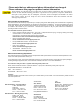
Please note that our address and phone information has changed. Please reference this page for updated contact information. These manuals are obsolete and are provided only for their technical information, data and capacities. Portions of these manuals detailing procedures or precautions in the operation, inspection, maintenance and repair of the products may be inadequate, inaccurate, and/or incomplete and shouldn’t be relied upon.
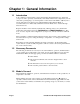
Chapter 1: General Information 1-1 Introduction Your portable hot oil temperature control unit circulates thermal transfer-type oil through your process and to precisely, automatically, and reliably maintain it at a temperature you can select. The operating range of your temperature control unit is from 100°F to 550°F (38°C to 288°C). The unit is best suited for use with TrueTherm™ Heat Transfer Fluid.
1-4 1-5 Standard Features • Off-the-shelf microprocessor-based PID temperature controller with Process and Set Point LED readouts • 6kW low watt density immersion heater with IEC contactors • 400°F (204ºC) maximum operating temperature • Branch fusing • System status graphic display • NEMA 1 electrical enclosure • 2 gallon (8 liter) expansion tank • To Process pressure gauge • Independent safety thermostat with safety contactor • Pressure actuated bypass • Positive displacement pumps
Heater Tank The portable hot oil temperature control unit features a single pass heater tank. The tank is designed to maintain an optimum balance of fluid velocity versus watt density, and turbulence for excellent heat transfer, and minimal pressure drop. The high fluid velocity will greatly prolong the life of the heater and fluid. Pump The pump is a mechanical seal, positive displacement pump.
The controller automatically regulates cooling by opening and closing the cooling solenoid valve. This allows the proper amount of cooling water to pass through the tubes of the heat exchanger and out the drain. A water supply of 75 psi (517.1 kPa/5.2 bars) maximum is required for connection to the heat exchanger. Connection Lines Connections for TO PROCESS and FROM PROCESS lines are ¾" NPT. Water connections for COOLING WATER SUPPLY is ½" and COOLING WATER DRAIN is ¾” NPT. (see Section 3.
circuit overcurrent and thermal overload protection. Many additional features are available as options. A NEMA 1 enclosure is standard. Venting Upon initial start-up and mold/process change-out, you’ll need to purge all air and water from the system. The unit has appropriate valving to ensure complete purging; procedures are covered in Section 4 on Page 26. ! WARNING Failure to purge the system of air before heating may result in serious injury or critical system and equipment damage.
! WARNING The reservoir tank may cause serious injury if it ruptures from not being properly vented. Make sure that the reservoir tank is always properly vented to prevent tank rupture.
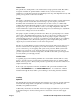
Figure 1 Portable Hot Oil Temperature Control Unit Portable Hot Oil Temperature Control Unit Specifications Model Number Available heaters 460 / 230 6 kW 6010 Std. Page 12 Power hp Pump Pressure Flow Dimensions W H D Shipping Weight kW PSI Bar gpm lpm in. mm in. mm in. mm lbs. Kg 0.75 0.56 50 3.45 6 22.
Chapter 2: Shipping Information 2-1 Unpacking and Inspection You should inspect your portable hot oil temperature control unit for possible shipping damage. If the container and packing materials are in re-usable condition, save them for reshipment if necessary. Thoroughly check the equipment for any damage that might have occurred in transit, such as broken or loose wiring and components, loose hardware and mounting screws, etc.
2-3 If the Shipment is Not Complete Check the packing list. The apparent shortage may be intentional. Back-ordered items are noted on the packing list. You should have: ; Portable hot oil temperature control unit ; Bill of lading ; Packing list ; Operating and Installation packet ; Electrical schematic and panel layout drawings ; Component instruction manuals Re-inspect the container and packing material to see if you missed any smaller items during unpacking.
Chapter 3: Installation 3-1 Work Rules The installation, operation, and maintenance of this equipment must be conducted in accordance with all applicable work and safety codes for the installation location. This may include, but is not limited to OSHA, NEC, CSA, and any other local, national, and international regulations. 3-2 • Read and follow these instructions when installing, operating, and maintaining this equipment.
! CAUTION Harmful vapors may be generated from thermal fluid during high temperature operation. Prolonged or repeated exposure of these hot-generated vapors may result in eye and respiratory tract irritation. Avoid contact or inhaling harmful amounts of material. Consult the Material Safety Data Sheet (MSDS) for precautions and instructions for the thermal fluid you are using.
The following table lists hot oil TCU pipe sizes. Size diameter Connection inches NPT To Process ¾” NPT From Process ¾” NPT Cooling Water Supply ½” NPT Cooling Water Drain ¾” NPT Fill Port 1” NPT c Customer is responsible for converting to metric. Notes: Always use a backup wrench to support the unit piping when making connections. Make sure all external piping is supported independently of the unit.
Connecting Process Piping ! CAUTION • Hoses, valves and other components in your process must be able to withstand temperature control unit maximum temperatures and pressures. • Maximum temperatures and pressures are listed on the unit nameplate. • Carefully inspect all components before installation. • If in doubt about component suitability, obtain factory components. • Fix all leaks! Fluid can be a potential fire and slip hazard.
! CAUTION The reservoir tank must be vented to prevent pressurization. A pressurized reservoir could rupture, allowing hot fluid to escape and become a potential fire and slip hazard. Note: Heat transfer fluids expand when heated. Expansion rates vary, depending on fluid types and temperatures. For more information on expansion rates, refer to specification information for the heat transfer fluid you select. Generally, most heat transfer fluids expand at the rate of 2.
Connect the TO PROCESS hookup to the entrance of the process and the FROM PROCESS hookup to the exit of the process. Connect the COOLING WATER SUPPLY to your plant water supply. Connect the COOLING WATER DRAIN line to an open drain, or to the return line of your central water system. If returning to a central water system, use a condensate/return tank to avoid a standing water column on the heat exchanger drain line.
• Locate disconnects in an easily accessible location. Operators should not have to squeeze around the unit to reach disconnects, especially in case of emergency. • When running conduit whips to the unit, make sure that whips are routed away from hot piping.
- Notes - Page 22 Portable Hot Oil Temperature Control Units
Chapter 4: Startup Preparations 4-1 Starting the Unit Unit Start-up The highly engineered controls and controller make this unit almost self operating. Before you can begin heating, it will be necessary to perform the following start up procedures. This will ensure that all air is vented from the system to prevent fluid degradation and damage to the heater. 1. Add fluid to the reservoir tank until the level is near the top of the sight glass. 2. Open the Vent Valve on the back of the unit. 3.
9. When fluid level has stabilized and air and water is purged from the system, close the Vent Valve. Do not open the Vent Valve above 250°F. With the system properly purged, only 2 - 3" of fluid should be visible in the sight glass. This will allow for expansion of the fluid as it heats, as well as capacity for process fluid when the pump is reversed and fluid withdrawn from the mold. The portable hot oil temperature control unit is now ready for use.
5. Watch the sight glass to prevent overflow of the reservoir tank. If it appears that the tank may overfill, connect a line from the FILL port of the reservoir tank to a clean auxiliary container.
- Notes - Page 26 Portable Hot Oil Temperature Control Units
Chapter 5: Using Controls & Indicators 5-1 The Microprocessor Controller The controller is an easy-to-operate microprocessor-based PID control device. When the process reaches the set point, the PID control cycles the cooling valve and/or immersion heater to maintain the proper leaving water temperature. The controller has been fully factory tested. Set the desired process temperature set point and the control does the rest. Built-in range of operation on the controller is 0°F to 550°F (-18ºC to 288ºC).
Setpoint Numeric LED During normal operation, the setpoint LED on the controller displays the process set point you want the chiller to maintain. It also displays parameter and pre-set function values during setup. RUN LED The RUN LED lights when the controller is in the “Run mode.” HIGH HEAT LED The HIGH HEAT LED lights when the controller output energizes the high heat heater contactor. LO HEAT LED The LO HEAT LED lights when the controller output energizes the low heat heater contactor.
Important! Do not change any of the control settings without consulting the Service Department. The manufacturer warranty does not cover TCU failures from tampering with controller settings! Index Key Pressing the Index Key advances the display to the next menu item. Down Key Each press of the Down key decrements or reduces the values or settings on the setpoint display when the Down key and the Setpoint key are pressed together.
! CAUTION After you silence the alarm, make sure you locate and correct the alarm condition before continuing with unit operation. . Indicator Lights Power On Indicator Light The Power On indicator light illuminates to indicate that the control circuit is energized in the unit. Pump Run The Pump Run indicator light illuminates to indicate the control power to the pump starter is energized.
Chapter 6: Preventive Maintenance ! WARNING Make sure that your maintenance technicians comply with lock-out/tag-out procedures during any servicing or maintenance of this unit and related equipment, per OSHA article ART 1910.147. Before you begin servicing this unit, disconnect all power to the unit, let the unit cool down completely, and turn off the water.
Making Six-Month Checks • Inspect electrical connections for secure, tight electrical terminations and ground connections. Inspect the power cable, especially at the entrance point to the electrical enclosure. Have a qualified electrician perform this inspection. 6-2 • Check the mounting bolts on the pump, the motor, and the heater flange for tightness. • Remove the heat exchanger tube bundle and check it for lime and mineral deposits. Carefully clean the bundle as needed.
6-4 Corrective Maintenance Pumps and Seals Each unit is completely tested and calibrated before leaving the factory. The unit is then cooled, drained, and packed for shipment. If the unit stands idle for a long time before being installed in your factory, gaskets can dry out and possibly leak when you start the unit. In most cases, these gaskets soon swell and form a tight seal. If not, you may need to tighten the bolts to stop the leak.
Disassembling the Pump 1. Mark head and casing before disassembly to insure proper reassembly. The idler pin, which is offset in pump head, must be positioned toward and equal distance between port connections to allow for proper flow of liquid through pump. Remove head from pump. Do not allow idler to fall from idler pin. Tilt top of head back when removing to prevent this. Avoid damaging head gasket. 2. Remove idler and bushing assembly. 3.
10. Remove the mechanical seal parts from the bracket. 11. Clean all parts thoroughly and examine for wear and damage. Check lip seals, ball bearing, bushings and idler pin and replace if necessary. Check all other parts for nicks, burrs, excessive wear and replace if necessary. Wash bearings in clean solvent. Blow out bearings with compressed air. Do not allow bearings to spin; turn them slowly by hand. Spinning bearings will damage race and balls.
3. Coat idler pin with non-detergent SAE 30 weight oil and place idler and bushing on idler pin in head. If replacing with carbon graphite bushing, Refer to Installation of Carbon Graphite Bushings. 4. Using a .010 to .015 inch head gasket, install head and idler assembly on pump. Pump head and casing were marked before disassembly to insure proper reassembly.
seal face. 7. Apply Dow Corning #44 high temperature silicon grease to the lip seal area in the seal gland and install on the shaft. Install the seal gland plate and secure with two nuts. 8. Pack ball bearing with Dow Corning #44 high temperature silicon grease and install in the thrust bearing housing. Place bearing spacer collars inside the lip seals. Thread the end cap into the bearing housing and tighten with a spanner wrench. Tighten the radial set screws that lock the end cap in place. 9.
*Each small notch on outer end cap represents .001 inch end clearance. ! WARNING Before starting the pump, make sure that all drive equipment guards are in place! Failure to properly install the guards may result in serious injury or death! Installation of Carbon Graphite Bushings When installing carbon graphite bushings, extreme care must be taken to prevent breaking. Carbon graphite is a brittle material and easily cracked. If cracked, the bushing will quickly disintegrate.
Lubricating the Pump Using #2 ball bearing grease and a hand-operated grease gun, gently lubricate all grease fittings after every 500 hours of operation or after 60 days, whichever comes first. If pump service occurs in severe conditions, lubricate more frequently. Use an appropriate type of grease for hot or cold applications. Adjusting End Clearance After long periods of service, the running clearance between the end of the rotor teeth and head may be increased from wear.
Page 40 Portable Hot Oil Temperature Control Units
Figure 5 Customer Recommended Spare Parts Immersion Heaters Part number 722-00108-33 722-00108-27 722-00108-32 722-00108-37 Description 6kW, 208V 6kW, 230V 6kW, 460V 6kW, 575V Note: 6 kW heaters are modified 12 kW heaters; jumpers are remove from one leg.
Figure 5 Customer Recommended Spare Parts Cont’d. Pressure Switch Part number 733-00018-00 Description Heat Exchanger Part number 106-00024-00 Description 1.5 SQ. FT.
Figure 5 Customer Recommended Spare Parts Cont’d. Controller Part number 601-00521-05 Description 6010 Selector Switches Part number 717-10029-00 717-10034-00 717-10028-00 Description ROCKER, WHITE (2 POSITION) HEAT/COOL CONTROL ROCKER, WHITE (MOMENTARY) Control Fuse Part number 725-00600-00 Description #FNM 1.
Figure 8 Customer Recommended Spare Parts Cont’d. Solenoid Part number 732-00013-00 732-00072-00 Description ¾", 120V ½", 120v Contactors Part number 729-00045-00 729-00084-00 729-00089-00 Description 30A 35A 60A Motor Starter Part number 726-00005-02 Description SIZE “00” Transformer Part number 704-00052-00 Description 230V/460V PRIMARY Ful-Flo Relief Valve Part number 044-00292-00 Description Note: Please give model and serial numbers when ordering parts.
7 Troubleshooting Condition Possible cause Undersized connectors/lines. Long connecting lines between unit and mold. Serpentine flow through mold. Blocked line in mold. Temperature fluctuations/rapid cycling from hot to cold. Quick disconnect fitting with check valve. Carbon build-up in unit piping or fittings. Faulty TCU. Reversed probes. Loss of fluid in process. Vent valve open. Unit does not heat properly/can not achieve set point.
Troubleshooting Cont’d. Condition Unit does not heat. (cont’d.) Unit overheats/unable to cool. Possible cause Controller heater output open. Clogged Y strainer. Water supply to unit is turned OFF. Water drain is plugged or excessive back pressure in drain line. Heat exchanger tubes plugged by lime deposits. Faulty solenoid valve. Leaks in connecting lines. Air in circulating lines. Low fluid. Defective Ful-Flo valve. Rapid drop in pressure/no pressure. Water in fluid. Vent solenoid open.
DIAGRAMS FLOW & ELEMENTARY ELECTRICAL Please refer to Electrical Drawings Provided in Packet with Unit Portable Hot Oil Temperature Control Units Page 47
Service Notes Page 48 Portable Hot Oil Temperature Control Units
Service Notes Portable Hot Oil Temperature Control Units Page 49
Service Notes Page 50 Portable Hot Oil Temperature Control Units
Service Notes Portable Hot Oil Temperature Control Units Page 51
Service Notes Page 52 Portable Hot Oil Temperature Control Units
Technical Assistance I Parts Department Call toll-free 7am–5pm CST [800] 423-3183 or call [262] 641-8610, Fax [262] 641-8653 The ACS Customer Service Group will provide your company with genuine OEM quality parts manufactured to engineering design specifications, which will maximize your equipment’s performance and efficiency. To assist in expediting your phone or fax order, please have the model and serial number of your unit when you contact us.