SDAA 25-100 Small Dryer With AP-1 Controls Part Number: 882.00294.00 Bulletin Number: DH1-610-2 Effective: 05/15/06 Write Down Your Serial Numbers Here For Future Reference: _________________________ _________________________ _________________________ _________________________ _________________________ _________________________ We are committed to a continuing program of product improvement. Specifications, appearance, and dimensions described in this manual are subject to change without notice.
Shipping Information Unpacking and Inspection You should inspect your portable drying/conveying system for possible shipping damage. Thoroughly check the equipment for any damage that might have occurred in transit, such as broken or loose wiring and components, loose hardware and mounting screws, etc. In the Event of Shipping Damage According to the contract terms and conditions of the Carrier, the responsibility of the Shipper ends at the time and place of shipment.
Table of Contents CHAPTER 1: SAFETY ................................................................ 6 1-1 1-2 1-3 1-4 How to Use This Manual ............................................................................................. 6 Safety Symbols Used in this Manual .....................................................................6 Safety Tag Information ................................................................................................ 7 Dryer Safety Tags ...........................
-2 4-3 Disconnect Switch ......................................................................................21 Control Power Switch .................................................................................21 Touch Screen .............................................................................................21 Alarm Horn & Light .....................................................................................21 Process Air Temperature Controller ........................................
Replacing the Process Heater.............................................................................45 Replacing/Cleaning the Cooling Coils .................................................................46 CHAPTER 6: TROUBLESHOOTING ........................................ 48 6-1 6-2 Introduction................................................................................................................ 48 Determining Temperature Controller Errors or Sensor Errors................................
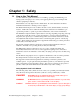
Chapter 1: Safety 1-1 How to Use This Manual Use this manual as a guide and reference for installing, operating, and maintaining your drying system. The purpose is to assist you in applying efficient, proven techniques that enhance equipment productivity. This manual covers only light corrective maintenance. No other maintenance should be undertaken without first contacting a service engineer. The Functional Description section outlines models covered, standard features, and safety features.
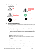
1-2 Safety Tag Information Dryer Safety Tags Hot! Read Operation and Installation Manual High Voltage Earth Ground Inside Enclosure PE Lifting Point 1-3 Protected Earth Ground Warnings and Precautions Our equipment is designed to provide safe and reliable operation when installed and operated within design specifications, following national and local safety codes. This may include, but is not limited to OSHA, NEC, CSA, SPI, and any other local, national and international regulations.
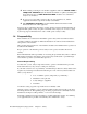
; When welding or brazing in or around this equipment, make sure VENTILATION is ADEQUATE. PROTECT adjacent materials from flame or sparks by shielding with sheet metal. An approved FIRE EXTINGUISHER should be close at hand and ready for use if needed. ; Do not restore power until you remove all tools, test equipment, etc., and the equipment and related components are fully reassembled. ; Only PROPERLY TRAINED personnel familiar with the information in this manual should work on this equipment.
Please read and use this manual as a guide to equipment safety. This manual contains safety warnings throughout, specific to each function and point of operation. Operator Responsibility The operator’s responsibility does not end with efficient production. The operator usually has the most daily contact with the equipment and intimately knows its capabilities and limitations.
• NEVER stand or sit where you could slip or stumble into the equipment while working on it. • DO NOT wear loose clothing or jewelry, which can be caught while working on the equipment. In addition, cover or tie back long hair. • Clean the equipment and surrounding area DAILY, and inspect the machine for loose, missing or broken parts. • Shut off power to the equipment when it is not in use. Turn the switch to the OFF position, or unplug it from the power source.
Chapter 2: Functional Description 2-1 Models Covered in This Manual This manual provides operation, installation, and maintenance instructions for 15, 30 or 60 cfm dehumidifying dryers. Model numbers are listed on the serial tag. Make sure you know the model and serial number of your equipment before contacting the manufacturer for parts or service.
2-3 Standard Features Mechanical Features • Rugged compact cart with handles and sturdy 4” (10 cm) casters. • Dual desiccant beds • Electrically-motorized air valve • 13X Molecular Sieve • Single regenerative process blower • Drying temperature range of 180ºF to 250ºF (82ºC to 121ºC) • 2.5” hose connections Electrical Features • Process thermocouple to be connected to drying hopper air inlet.
2-4 Options Options marked with “*” indicate options that can be factory installed or retrofitted in the field. • * Process temperature up to 400ºF (204º C), including aftercooler with dryer and silicone insulated delivery hose. Note: For below 180°F (82ºC), cooler needs to cool the air coming out of the desiccant tank prior to entering the process heater box. • * If the dryer is a central dry air generator, it will not have a process heater box.
Every effort has been made to incorporate these standards into the design of the drying system; however, it is the responsibility of the personnel operating and maintaining the equipment to familiarize themselves with the safety procedures and the proper use of any safety devices. Fail Safe Operation If a safety device or circuit should fail, the design must be such that the failure causes a “Safe” condition. As an example, a safety switch must be a normally open switch.
Chapter 3: Installation 3-1 Uncrating the Equipment Portable Drying/Conveying Systems are shipped mounted on a skid, enclosed in a plastic wrapper, and contained in a cardboard box. 1. Pry the crating away from the skid. Note: Remove the nails holding the box to the skid and lift the box off carefully; avoiding staples in the 1’ x 4’ wood supports. Cut the steel banding. 2. Use a pry bar to remove the blocks securing the unit to the skid. 3. Lift unit from sides.
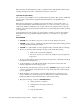
Figure 1: Suggested Lift Rigging for Cart Mount Dryers DO NOT USE DEW POINT ALARM HORN ALARM ALARM Silencer OFF ON PROCESS TEMPERATURE CONTROL POWER ON OFF USE FORK LIFT TRUCK Caution! Do not use a hoist to move or rig your Drying/Conveying System when it is mounted on a cart! Moving the unit with a hoist will cause it to become unstable and may cause damage to the equipment and/or injury to personnel! Figure 2: Suggested Lift Rigging for Cart Mounted Dryers Note: Floor Mounted Dryers can be li
Figure 3: Suggested Lift Rigging for Cart Mounted Dryers Mounting flange E E Diameter hole: F ON DEW POINT CONTROL POWER ON OFF ALARM HORN ALARM ALARM Silencer Notes: Hopper mounting flanges on 0.75 and and 1.5 cu. ft. (20 & 40 liter) hoppers are supplied blank so the customer can drill to match existing machine throat. OFF PROCESS TEMPERATURE 3.0 cu. ft. (80 liter) hoppers and larger are not supplied with a cast flange (as shown).
3-4 Setup Procedures This section provides the procedures necessary for configuring your portable drying/conveying system. Configuration of your unit includes checking for proper blower rotation and installing the optional aftercooler (on 60 cfm models). We recommend that you carry out these procedures in the order given here. Note: Before carrying out these procedures, install all equipment as described in this section.
NOTE: If the Aftercooler is used as a plasticizer trap, the water temperature of 50°F or lower is recommended. 3-5 Initial Start-up Pre-Startup Checks ; Check the process and return hoses for tight connections. ; Check all companion equipment, such as the drying hopper; verify that the loading system is ready for operation. ; Verify that all dryer electrical connections are tight. ; Verify that the thermocouple is properly installed at the hopper inlet. Starting Up the Dryer 1.
Figure 2: Process Autotune Screen 1. The autotune feature can be enabled by pressing the START/STOP button located in the center of the screen. 2. AUTOTUNE IN PROGRESS or PROCESS NOT ACTIVE will inform the operator of the current status of this feature. 3. At this point the operator can return back to the DRYER MENU or MAIN MENU by touching the appropriate button on the screen. Shutting Down the Dryer 1. Turn off the conveying system supplying the drying hopper and/or machine.
Chapter 4: Operation 4-1 Controller Description and Operation Identifying Control Panel Components for the AP-1 Controller Disconnect Switch The Disconnect Switch is located in the front upper right hand corner of the control enclosure. It allows the user to disconnect power to the dryer for emergency shutdown, service or long periods of inactivity. Control Power Switch The Control Power Switch is located on the front of the control enclosure below the touch screen.
Process Air Temperature Controller Control package use a PLC with a touch screen interface to control the operation of the dryer and the optional conveying system. This section of the manual will address those parameters that allow the user to optimize the drying/conveying system for specific applications.
Main Menu Screen The MAIN MENU provides information on the following drying/conveying system parameters: • DRYER MENU (some submenus are password protected) • ALARM HISTORY • HELP MENU • SYSTEM MENU • NO USERS LOGGED ON This section of the manual will focus on the dryer features portion of the controller at this time. Press the DRYER MENU button to return to the next section of dryer functions.
Machine Status The area in the lower left portion of the touch screen conveys two lines of information relating to the overall operation of the dryer. The following is a list of typical machine/dryer summary status line text messages: 1. Left Bed In Process 8. Left Bed Heat 2. Right Bed In Process 9. Left Bed Cool 3. Process Offline 10. Left Bed Ready 4. Valve Changing Position 11. Right Bed Heat 5. Auto start Timer Enabled 12. Right Bed Cool 6. Autotune in Progress 13. Right Bed Ready 7. 14.
Dryer Menu Screen The screen shown above will allow the operator to set/review operating parameters for the following: • DRYER STATUS • DRYER SETUP (requires supervisory password) • OVERDRY PROTECT (requires supervisory password) • ALARMS • AUTO TUNE (requires supervisory password) • DEW PT SETUP (Dew Point Setup) • AUTO START (requires supervisory password) • MAIN MENU DRYER STATUS Pressing the STATUS button will take the operator back to the original status screen shown on page 27.
Buy pressing the MORE screen, you can choose for the temperatures to display in degrees F or degree C. (Note; Changing the temperature scale, requires adjusting the alarm values.) When these settings have been made, the operator now has a choice of returning to the DRYER MENU, BACK (takes you back to the DRYER SETUP 1 of 3) or pressing MORE to take you to screen 3 of 3 of the DRYER SETUP screen.
The PROCESS RETURN AIR TEMPERATURE displays the air temperature as it leaves the drying hopper. If this temperature is above 150°F, an aftercooler is required. By pressing the DISABLE or ENABLE the operator disable or enable this feature of the dryer. This feature is used to prevent the over drying of the plastic resin in the drying hopper. At this point the operator has the choice of pressing MAIN MENU, DRYER MENU, or MORE to access the screen 2 of 2 of the OVERDY PROTECTION for adjusting values.
Enter the values you would like to set in the screen by pressing the number keys. Press ENT (Enter) when you are finished to set the new values or CLR (Clear) to erase the current values and reenter new ones. The next feature in the DRYER MENU is the ALARMS button/screen. Alarms (Retains 100 of the most recent alarms) This screen allows the operator to review the number and type of issues that the Dryer has encountered during its operation. The “Alarm History” screen is NOT reset-able.
Dew Pt Setup This screen allows the operator to set the dew point alarm value. The HIGH LIMIT ALARM VALUE is an audible/visual alarm which will sound when the process air dew point rises to this value. Values can be set for degrees Fahrenheit between – 40 through +15 degrees and degrees Celsius between -40 through -10 degrees.
By touching the ON TIME and OFF TIME sections on the screen, the operator can enter the values for the time they wish the dryer to turn on and off. See the next page for instructions on setting values for this feature. Pressing the AUTOSTART TIMER DISABLED button will activate this dryer feature. Pressing AUTOSTART TIMER ENABLED will deactivate this feature. Once this feature has been set, the operator can return back to the DRYER MENU or MAIN MENU by touching the appropriate button on the screen.
System Menu The screen shown above will allow the operator to set/review operating parameters for the following: The above screen will allow the operator to set/review operating parameters; • SYSTEM SETUP • SET CLOCK • HOUR METERS • ALARM HISTORY • I / O STATUTUS (Input and output status) • SYSTEM BACKUP • SERVICE • MAIN MENU SYSTEM SETUP This screen allows the operator to set alarm and password features.
Note: If password(s) feature is enabled, please write down your passwords and file them in a secure location. At this point the operator can return back to the MAIN MENU or SYSTEM MENU by touching the appropriate button on the screen. Set Clock This menu allows the operator to set the AUTOSTART CLOCK and the ALARM CLOCK. Press the SET AUTOSTART CLOCK or the SET ALARM CLOCK buttons to set the times and dates on these features.
Set Alarm Clock In this screen the user can set the variables which are used to time and date stamp alarms. This feature works in conjunction with the ALARM screen (See page 31) to notify the user of issues which the Dryer had encountered during its operation. Setting Values Pressing the individual numbers in the second row of the screen shown above, the operator can select the field (Month, Day, Year, Hours and Minutes) he wishes to change.
Input Status (UPDATE) This screen allows the operator to view the status of the variables contributing to the input of material into the drying system. It also is useful in troubleshooting system issues (i.e. a dirty filter or low material level in a hopper). At this point the operator may choose the SYSTEM MENU button to go back to the system menu, or MAIN MENU to return to main menu, or press OUTPUTS to access the output screen.
At this point the operator may choose to return to the SYSTEM MENU or MAIN MENU by pressing the appropriate buttons. Service Menu This service menu screen is PASSWORD PROTECTED and meant for manufacturer personnel use only. Press the RETURN key to go back to the SYSTEM MENU. Touching the MAIN MENU button in the SYSTEM MENU screen, will return the operator back to the overall menu screen.
Because of the size of the screen, only three (3) comments/alarms can be viewed at a time. To view alarms not visible on the screen, press the DOWN button. To return to a particular alarm, press the UP button to scroll upward in the alarm history. Pressing CNV (Convey) in this screen will take the operator to the CONVEY STATUS of the system. You will only get CNV alarms with a Nomad dryer.
lower display indicates the High Point Setting alarm value. The factory setting for the High Point Alarm Value (L1-hi ) is 150°F (-23°C). Restoring the WATLOW Redundant Safety Controller to Factory Setup If the preset parameters on the controller have been tampered with and it no longer functions properly, call the Service Department. Note: This controller is not meant to be modified. WATLOW Operating Parameters The WATLOW controller has only one mode selection; ALARM.
UdSP Upper Display Look LdSP Lower Display Look LOC Lockout None, Process Value, Limit 1 Low Set, Limit 1 High Set, Limit 2 Low Set, Limit 2 High Set, Alarm 2 Low Set, Alarm 2 High Set, Limit 3 Low Set, Limit 3 High Set, Alarm 3 Low Set, Alarm 3 High Set None, Process Value, Limit 1 Low Set, Limit 1 High Set, Limit 2 Low Set, Limit 2 High Set, Alarm 2 Low Set, Alarm 2 High Set, Limit 3 Low Set, Limit 3 High Set, Alarm 3 Low Set, Alarm 3 High Set (0) no lockout, (1) Programming and Setup Page Locked, (
4. If either the left or right bed safety temperature switch opens, a REGEN TEM SAFETY is generated. The alarm horn and light are activated. The process heater, regen heater, and process/regen blower are turned off. Pressing the ALARM SILENCE button on the touch screen will deactivate the alarm horn and light. 5. Turn the Off-On switch to the ON position and push the touch screen START button to restart the dryer. If the switch is still open, the dryer will not restart. 6.
Chapter 5: Maintenance 5-1 Preventative Maintenance Schedule The checklist below contains a list of items which should be inspected and/or replaced to keep your Portable Drying/Conveying System operating at peak efficiency. Perform each inspection at the regular intervals listed below.
5-2 Preventative Maintenance This section describes maintenance procedures which will increase the longevity and efficiency of your Portable Drying/Conveying System. Perform them at the regular intervals listed on the checklist on the previous page. Servicing Process Air Filters Caution! Operating the dryer without the process air filter installed voids your warranty! Filter cleaning is an important part of your dryer maintenance program.
Vacuuming Try vacuum-cleaning a soiled filter first. Vacuuming removes most large particles and surface contaminants, and may suffice for the first time you clean a filter. Use a commercialduty (recommended) or household vacuum cleaner. Vacuum the filter from the air intake (dirty) side only. Cleaning with Compressed Air Blow clean, dry compressed air up and down the pleats, blowing out the filter from the inside out. Remove loose dirt from the filter with compressed air or vacuum from the outside.
5-3 Corrective Maintenance This section provides you with the information necessary to correct or repair any issues which might appear during the normal operation of your dehumidifying dryer. Although we have listed how to perform these procedures, it is recommended that you call the Service Department to have any in-depth maintenance performed. Symptoms of Worn Desiccant The moisture absorption capacity of the desiccant used in your dehumidifying dryer degrades after an indefinite period of time.
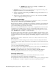
Figure 8: Desiccant Bed Location and Disassembly Undo (4) 10-32 Button Head Screws using 1/8 Allen Wrench Desiccant Cap 1" Wide x 1/8" Thick Silicon Strip and Stick Gasket 13X Molecular Sieve 8x12 Beads Regeneration Heater Regeneration Thermocouple 16 Mesh 0.028 Diameter Wire Stainless Steel Screen (2) 4-40 screws Hi Temperature Snap Switch 1" Wide x 1/8" Thick High Temperature Gasket Caution! You should properly dispose of any discarded desiccant.
Figure 9: Required Desiccant Amounts Dryer model 15 cfm 30 cfm 60 cfm 8 x 12 bead Total Part no. lbs. 7.0 W00018051 15.75 37.5 Kg 3.25 7.25 17.0 Replacing the regeneration heaters Procedures (see figure 8). 1. Sketch the heater wiring configuration so you can properly re-wire the heater. 5 Remove the ceramic nuts and wires to the heater plate assembly being removed or replaced.
Procedures 1. Sketch the heater wiring configuration so you can properly re-wire the heater. 2. Remove the ceramic nuts and wires to the heater plate assembly being removed or replaced. 3. Remove the six (6) 10-32 button head screws securing the process heater plate using a 1/8” Allen wrench and slide out the assembly. 4. Remove the heater(s) from the mounting plate by removing the large brass nuts and washers. 5. Re-install the heater(s) and heater plate assemblies in reverse order.
Replacement Procedures 1. Shut down the dryer, tag out and lock out the controls if necessary. 2. Shut the water off to the cooling coil. 3. Remove the four 10-32 bolts. 4. Gently slide the cooling coil out. 5. Visually inspect the coil for leaks, dirt, and ant sign of volatiles. 6. Blow the dust out, or if the coil is covered with plasticizer, steam clean it. 7. Place the coil back in its housing. Make sure the gasket is OK, replace if necessary. 8. Inset the four 10-32 bolts back in place. 9.
Chapter 6: Troubleshooting 6-1 Introduction The utmost in safety precautions should be observed at all times when working on or around the machine and the electrical components. All normal trouble-shooting must be accomplished with the power off, line fuses removed, and with the machine tagged as out of service. The use of good quality test equipment cannot be over-emphasized when troubleshooting is indicated.
Alarm Message PROCESS SENSOR FAIL Cause The process temperature thermocouple is open. Dryer Status The process temperature thermocouple is not connected to the temperature controller. Make sure the connections are correct and tight. - Dryer Shuts Down: - Process blower OFF. - Process heaters OFF. - Regen heaters OFF. - Alarm light is ON - Alarm horn is ON. The process temperature thermocouple is damaged. Replace the thermocouple.
Alarm Message PROCESS SENSOR FAIL Cause The process temperature thermocouple is open. REGEN SENSOR FAIL The Regeneration temperature thermocouple is open. PROCESS HIGH TEMP The process temperature has exceeded the alarm set point. Portable Drying/Conveying Systems Corrective Action Dryer Status The process temperature thermocouple is not connected to the temperature controller. Make sure the connections are correct and tight. - Dryer Shuts Down: - Process blower OFF. - Process heaters OFF.
Alarm Message Cause Corrective Action Dryer Status REGEN LOW TEMP The regeneration temperature did not get within the alarm set point. - Dryer Normal : - Process blower ON. - Process heaters ON. - Regen heaters ON. - Alarm Message ON. - Alarm horn is OFF. PROCESS LOOP BREAK The process drying air temperature has not made any improvement toward the drying temperature set point for more than 480 seconds. HIGH DEW POINT The dew point reading has exceeded the dew point alarm set point.
Alarm Message Cause Corrective Action Dryer Status PROCESS BLOWER FAIL The process blower pressure switch did not detect enough pressure. Make sure the process air filter is clean. Clean or replace if necessary. Check the rotation of the blower. Check the pressure switch hose connection. Replace hoses or the pressure switch. Check the over load rating against the wiring diagram. Adjust accordingly. Check the wiring of the blower. Make sure it is wired for the proper voltage.
Alarm Message Cause Corrective Action Dryer Status DIRTY FILTER The filter pressure differential switch has tripped. - Dryer Normal : - Process blower ON. - Process heaters ON. - Regen heaters ON. - Alarm Message ON. - Alarm horn is OFF. VALVE MOTOR FAIL The limit switch on the valve may not have been wired correctly. P RETURN SENSOR FAIL The return air temperature thermocouple is open or failed. PROCESS TEMP SAFETY The high temperature snap switch of the process heater box has tripped.
6-2 Determining Temperature Controller Errors or Sensor Errors Using a Thermocouple If the controller displays a temperature that is close to room temperature (70ºF/21ºC) when you short-circuit controller input terminals, the controller is normal and the sensor is probably broken, short-circuited, or incorrectly wired. Other service problems or questions can be answered by contacting the Service Department.
Chapter 7: Appendix 7-1 Warranty Unless otherwise specified, this product includes a Standard ONE YEAR PARTS. Warranty Specifications The manufacturer hereby expressly warrants all equipment manufactured by it to be free from defects in workmanship and material when used under recommended conditions, as set forth in the operating manuals for such equipment.
applicable federal and state law, but not by the United Nations Convention on Contracts for the Sale of Goods. Customer Responsibilities Any sales, use, or other tax incident to the replacement of parts under this warranty is the responsibility of the purchaser. 7-2 Optional Components The following is a list of options which your Portable Drying/Conveying System may have been equipped with: • High Temperature Option (with Aftercooler) • Casters.
22. 23. 24. 25. 26. 27. Two-hand control is not required or provided. All dryers and conveying equipment should be moved around and set in a place with a lift truck or equivalent. There are no frequent repetitive cycles that require manual control⎯repetitive functions are automatic while the drying and conveying system is operating. An inspection report detailing the functional test is included with the dryer and conveying system. The machine is not equipped with cable less controls.
Figure 13: High Heat Model (180°F to 400°F) Air Flow Schematic Pressure switch, makes sure the blower is functioning correctly. High pressure peripheral regenerative blower. Dryer valve 2” Hose Optional Return Air Cooler 2” Hose Utilizing -40F dew point air to regenerate and cool the desiccant. 2” Hose 13X Molecular Sieve 8x12 beads. Low watt density heaters, can operate safely with minimum air flow. Double wall constructed heater housing and desiccant container.
Figure 14: Low Heat Model (120°F to 250°F) Air Flow Schematic High pressure peripheral regenerative blower. Pressure switch, makes sure the blower is functioning correctly. Dryer valve 2” Hose Utilizing -40F dew point air to regenerate and cool the desiccant. 13X Molecular Sieve 8x12 beads. Double wall constructed heater housing and desiccant container.
7-5 Spare Parts List LEVEL 1 ( Mechanical Components ) PART # SIZE Description W00015435 Dew Point Sensor Insert Cable A0548556 Dew Point Sensor A0566467 Valve switch W0005247 Process Air Filter W00018051 13X molecular Sieve Desiccant ( 8 X 12 Beads ) W00013983 High Temperature Gasket. A0566676 High Temperature Snap Switch.
1 1 1 A0548555 1 1 1 4 5 0 0 0 0 0 7 0 0 0 0 0 * Dew Point Circuit Board LEVEL 2 ( Mechanical Components ) PART # SIZE Description A0548621 Ceramic Cap for the End of Heater Elements A0566478 750 Watts Heater element 208/220 Volts A0566479 750 Watts Heater element 230 Volts A0566480 750 Watts Heater element 400 Volts A0566481 750 Watts Heater element 460 Volts A0566482 750 Watts Heater element 575 Volts A0566483 1250 Watts Heater Element 208/220 Volts A0566484 1250 Watts Heater Element 230 Volts
7-6 Returned Material Policy Credit Returns Prior to the return of any material authorization must be given by the manufacturer. A RMA number will be assigned for the equipment to be returned. Reason for requesting the return must be given. ALL returned material purchased from the manufacturer returned is subject to 15% ($75.00 minimum) restocking charge. ALL returns are to be shipped prepaid. The invoice number and date or purchase order number and date must be supplied.
7-8 Technical Assistance Parts Department Call toll-free 7am–5pm CST [800] 423-3183 or call [630] 595-1060, Fax [630] 475-7005 The ACS Customer Service Group will provide your company with genuine OEM quality parts manufactured to engineering design specifications, which will maximize your equipment’s performance and efficiency. To assist in expediting your phone or fax order, please have the model and serial number of your unit when you contact us.