
ASX7-5-Installation Instructions
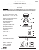
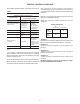
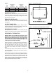
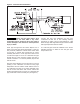
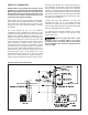
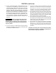

Figure 4 - Horizontal Vent Termination Location
AIR INLET COLLAR
Remove screen and mounting plate from air inlet on
rear panel of unit by removing 4 screws. Secure inlet
collar and gasket to inlet opening re-using the 4 screws
removed in previous step.
EXHAUST AIR COLLAR
Secure 5-4" reducer to ue collar on rear panel of unit
sizes 090, 105 and 120. Seal per exhaust venting
instructions.
ACCESS PANEL SEAL
Cut gasket to lengths listed in Table 2. Remove paper
backing and adhere to access panel making certain that
the entire perimeter is covered (Figure 3).
POWER SUPPLY INLET
After powerline is run to main control board, seal gap
between cord and hole in rear panel with silicone sealant.
HORIZONTAL TERMINATION
NOTICE: When using double wall vent pipe, O-ring
gaskets are not required and should be discarded.
When using single wall vent pipe, one O-ring should
be inserted in each of the ue pipe openings in the
Air Inlet Screen, Deector Disk and the top of the
Combustion Air Inlet Box Assembly.
Select a location on outside wall for vent terminal. In
most applications, the terminal should be on level
with the flue outlet of the unit, less a 1/4 inch per
foot (21mm/m) pitch for condensate drainage toward
the outside of the building. See Table 1 and Figures 4
and 5.
Cut hole through wall for 9 inch (229mm) combustion air
pipe. Install thimble if required by local codes or type of
wall construction.
Combustion air inlet box may be fastened directly to
wall or spaced away from wall using suitable brackets
(eld supplied). Cut length of 9 inch pipe so that it will
protrude 4 inches (102mm) through the wall when the
box is mounted in position. Fasten pipe to box with sheet
metal screws, using at least 3 screws per joint. Seal joint
with high temperature silicone sealant.
Figure 3 - Access Panel Seal
D-8615
Table 2
Top/Bottom Right/Left
Unit Gasket Gasket
Size Length (In) Qty Length (In) Qty
090 18 3/8 2 22 5/8 2
105 18 3/8 2 22 5/8 2
120 18 3/8 2 22 5/8 2
4