
ASX7-4-Installation Instructions

Improper installation, adjustment, alteration, service or maintenance can cause
property damage, injury or death. Read this supplement and the unit heater installation,
operating, and maintenance instructions thoroughly before installing or servicing this equipment.
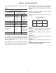
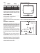
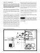
The location of the vent terminal must be in
accordance with the National Fuel Gas Code ANSI
Z223.1 (NFPA 54) in the U.S. or the Natural Gas
Installation Code CSA-B149.1 or the Propane
Gas Installation Code CSA-B149.2 in Canada.
Minimum clearances are shown in Table 1 and
Figures 4, 5 and 6.
This Combustion Air Inlet Kit utilizes one 4 inch
termination in which both the discharge ue gas
and the combustion air inlet pass.
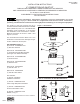
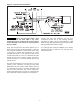
KIT CONTENTS (Figure 1)
(#1) Part No. 11J37R08571-001
(1) Flue Vent Terminal
(#2) Part No. 11507R06601-DBL
(1) Combustion Air Inlet Box Assembly
(see Figure 2 for dimensional data)
(#3) Part No. 11J37R06665-DBL
(1) Air Inlet Screen
(#4) Part No. 11507R06693-DBL
(1) Deector Disk*
(#5) Part No. 11257R08331
(1) Inlet Air Collar - 4"
(#6) Part No. 11262R08332
(1) Inlet Air Collar Gasket
Also Included:
(1) Part No. J30-08579
Installation Instructions
(1) Part No. 11H03R03612-002
Tube of High Temp Silicone Sealant
(1) Part No. 11262R08614-004
Access Panel Gasket - 68.5"
(3) Part No. 11H03R09471-004
Gasket, O-ring - 4"
*Deector disk comes with brackets and screws for installation.
10/18
ASX7-4-IOM-8
J30-08579
Figure 2 - Combustion Air Inlet Box Dimensions
Figure 1 - Kit Contents
D8618B
INSTALLATION INSTRUCTIONS
4" COMBUSTION AIR INLET KIT
TUBULAR GAS FIRED DIRECT SPARK PROPELLER UNIT HEATERS
UNIT CONVERSION & CATEGORY III VENTING FOR SEPARATED COMBUSTION
For 30,000 to 75,000 BTU/HR
SUPPLEMENT TO UNIT INSTALLATION INSTRUCTIONS
GG-IOM & 5S6935
D6875C