SF Series Additive Feeders Part No.: 882.00274.00 Bulletin No.: BF2-605.1 Effective Date: 5/2/08 Write Down Your Serial Numbers Here For Future Reference: _________________________ _________________________ _________________________ _________________________ _________________________ _________________________ We are committed to a continuing program of product improvement. Specifications, appearance, and dimensions described in this manual are subject to change without notice. DCN No.
Shipping Information Unpacking and Inspection You should inspect your additive feeder for possible shipping damage. Thoroughly check the equipment for any damage that might have occurred in transit, such as broken or loose wiring and components, loose hardware and mounting screws, etc. In the Event of Shipping Damage According to the contract terms and conditions of the Carrier, the responsibility of the Shipper ends at the time and place of shipment.
Table of Contents CHAPTER 1: SAFETY................................................................V 1-1 1-2 1-3 How to Use This Manual ............................................................................................. v Safety Symbols Used in this Manual ..................................................................... v Warnings and Precautions ......................................................................................... vi Responsibility .......................................
-4 Resetting the Unit to Un-Programmed State .......................................................25 JP1 (Program Enable Jumper) ............................................................................25 Programming Step by Step Guide.......................................................................25 Injection Mode Application Notes ........................................................................27 Extrusion Applications .................................................................
Chapter 1: Safety 1-1 How to Use This Manual Use this manual as a guide and reference for installing, operating, and maintaining your additive feeder. The purpose is to assist you in applying efficient, proven techniques that enhance equipment productivity. This manual covers only light corrective maintenance. No other maintenance should be undertaken without first contacting a service engineer. The Functional Description section outlines models covered, standard features, and safety features.
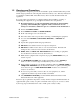
1-2 Warnings and Precautions Our equipment is designed to provide safe and reliable operation when installed and operated within design specifications, following national and local safety codes. This may include, but is not limited to OSHA, NEC, CSA, SPI, and any other local, national and international regulations.
1-3 Responsibility These machines are constructed for maximum operator safety when used under standard operating conditions and when recommended instructions are followed in the maintenance and operation of the machine. All personnel engaged in the use of the machine should become familiar with its operation as described in this manual. Proper operation of the machine promotes safety for the operator and all workers in its vicinity.
Operator Responsibility The operator’s responsibility does not end with efficient production. The operator usually has the most daily contact with the equipment and intimately knows its capabilities and limitations. Plant and personnel safety is sometimes forgotten in the desire to meet incentive rates, or through a casual attitude toward machinery formed over a period of months or years. Your employer probably has established a set of safety rules in your workplace.
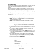
• Clean the feeder and surrounding area DAILY, and inspect the machine for loose, missing or broken parts. • Shut off power to the feeder when it is not in use. Turn the switch to the OFF position, or unplug it from the power source. Additive Feeder Safety Tags Read Operation and Installation Manual Shear Hazard Rotating Auger High Voltage Earth Ground Inside Enclosure PE Lifting Point Protected Earth Ground Maintenance Responsibility Proper maintenance is essential to safety.
When you have completed the repair or maintenance procedure, check your work and remove your tools, rigging, and handling equipment. Do not restore power to the equipment until all persons are clear of the area. DO NOT start and run the machine until you are sure all parts are functioning correctly. BEFORE you turn the machine over to the operator for production, verify all equipment enclosure panels, guards and safety devices are in place and functioning properly.
Chapter 2: Functional Description 2-1 Models Covered in This Manual This manual provides operation, installation, and maintenance instructions for 1 and 2 component additive feeders. Model numbers are listed on the serial tag. Make sure you know the model and serial number of your equipment before contacting the manufacturer for parts or service. Our additive feeders are designed to precisely feed up to two components before being used in the injection molding, blow molding or extrusion processes.
Motor Assembly • Quick release swing-away motor mount speeds auger/motor changes and cleanout • Permanently lubricated • Replaceable motor brushes Electrical Features Motor Assembly • Continuous service fractional horsepower DC motor. • Hall Effect sensor transmits RPM to microprocessor control • 115/1/60 supply voltage Controller Features • Closed-loop control constantly monitors feedback from the auger motor RPM sensor for high accuracy and repeatability.
Extruder Following Feature • This feature allows the additive feeder to automatically increase or decrease the material feed rate as the extruder screw speed changes. Quick Change Supply Hopper • 0.
Safety Circuit Standards Safety circuits used in industrial systems protect the operator and maintenance personnel from dangerous energy. They also provide a means of locking out or isolating the energy for servicing equipment. Various agencies have contributed to the establishment of safety standards that apply to the design and manufacture of automated equipment.
Chapter 3: Installation 3-1 Uncrating the Equipment Additive feeders are shipped mounted on a skid, and enclosed in a cardboard box. 1. Pry the crating away from the skid. Note: Remove the nails holding the box to the skid and lift the box off carefully; avoiding staples in the 1’ x 4’ wood supports. Cut the steel banding. 2. Use a pry bar to remove the blocks securing the unit to the skid. 3. Lift unit from sides. Use a pry bar if necessary to carefully remove the skid from the unit.
3-3 Electrical Connections When making electrical connections to your additive feeder, ensure that you take into consideration and make arrangements for the following: • A qualified electrician should make all electrical connections. • Fulfill all national, state, and local safety and electrical code requirements. • The serial tag lists voltage, phase, and amp draw information • Line voltage must be within plus or minus ten percent (±10%) of the voltage listed on the serial tag, or damage may occur.
3-4 Setup Procedures This section provides the procedures necessary for configuring your additive feeder. Configuration of your additive feeder includes determining the desired feed rate and calibrating the additive feeder. We recommend that you carry out these procedures in the order given here. Note: Before carrying out these procedures, install all equipment as described in this section.
Figure 1: Conversion Chart Multiply Ounces per Second Grams Ounces Seconds By 225 0.035 0.0625 0.
Calibration Procedure This procedure allows the operator to precisely adjust additive feed rates. Caution! Never put hands or tools in or near the auger assembly when power is connected. Do not wear gloves or loose clothing during calibration. The auger is exposed when the calibration or cleanout hatches are open. Equipment Needed: • Scale • Sample container • Timer- stopwatch, watch/clock w/second hand Procedure 1. Close cleanout and calibration hatches. 2. Fill the additive supply hopper. 3.
Examples: This example shows how to extrapolate a desired feed rate of 3 lbs./hr., based on the feed rates of 3 trial rpm settings. Observed Feed Rates Sample 1 = 2 pounds per hour @ 20 rpm Sample 2 = 4 pounds per hour @ 40 rpm Sample 3 = 6 pounds per hour @ 60 rpm In this example, a feed rate of 3 lbs./hr. would be about 30 rpm.
3-5 Initial Start-up Pre-Startup Checks ; Are all the electrical connections correct, secure and to code? ; Is the auger insert locked in place? ; Are the motor and auger properly coupled and the motor mount locked in place? ; Are the cleanout and calibration hatches shut and secured? ; Are all tools, hardware, etc.
Chapter 4: Operation 4-1 Start-up 1. Turn the power switch ON. 2. Set the desired feed rate on the RPM display using the up or down arrows. 3. Flip the motor switch to AUTO. If the additive feeder is installed correctly, it should begin operation at the desired RPM when the processing machine screw is in operation. 4-2 Controller Description and Operation Identifying Control Panel Indicator Lights and Switches on the Controller Switches Power Switch. This switch turns the control ON and OFF.
Procedure 1. Time the duration of feeder operation during a typical Injection molding machine shot cycle. 2. Set the timer to a slightly longer value. 3. Start the additive feeder by flipping the motor switch to the AUTO position. 4. If the timer times out because of a process flow problem, the feeder will automatically stop. 5. Reset the power switch.
4-3 Injection Molding Applications Discussed in this portion of the manual are the finer points of the additive feeder operation, programming the control, and installation notes and examples. If you are unfamiliar with this product or have never performed this type of installation, please read this section of the manual fully before installing the equipment.
editing purposes. Pressing the Up or Down button will increase or decrease the selected parameter number on the display. Although the parameter numbers are in numerical order, some numbers are skipped. These numbers represent reserved parameters that are not yet implemented and are not displayed. Once the desired parameter number is displayed, a press of the Enter button will change the display to the Value Mode.
7. Install the enclosure cover. 8. Remove any lockout/tagout devices in use as per procedures in place at your facility, then connect the controller to the power source and power the unit up. 9. Press the Enter button until parameter selection mode is entered. When the drive is in Parameter-Selection Mode, the far left of the display will be a “P.” 10. Use the Up and Down arrow buttons to navigate to the desired parameter. 11.
feeder. If you do not have these drawings contact service to have them forwarded to you. Injection Mode Application Notes The additive feeder controller has the ability to display feed rates in units other than the factory set auger RPM display. With proper programming, the feeder can display pounds/hour, grams/minute, etc. Programming for units other than auger RPM REQUIRES that the system be calibrated to determine exactly how much material is delivered at specific RPMs.
4-4 Extrusion Applications Discussed in this portion of the manual are the finer points of the additive feeder operation, programming the control, and installation notes and examples. If you are unfamiliar with this product or have never performed this type of installation, please read this section of the manual fully before installing the equipment.
Extruder Tracking Installation and Setup The additive feeder control is supplied with standard factory defaults. Control programming is required to suit the requirements of your process (See page 24, Field Control Programming). Connect the TTL signal acquired from the extruder control or from a sensor you have installed to the terminal strip as shown in the electrical schematics provided with your unit’s installation packet. 1. Install the feeder as described in Chapter 3. 2.
Field Control Programming Although the drive’s user interface is very versatile, it is also simple to setup and operate. With just a few button presses, it allows the user to configure a number of adjustable parameters. The LED display has three basic operating modes: Running Mode, ParameterSelection Mode, and Value Mode. Each of the three modes have specific visual indicators that allow the user to immediately determine the current state or mode of the user interface.
Resetting the Unit to Un-Programmed State The factory-default settings can be easily restored using either of two methods. Both methods require the Program Enable jumper to be in the “On” position. The first is to apply power to the unit with both the Enter and Down buttons pressed for 3 seconds. The second is to change the value of parameter 95 to 5. JP1 (Program Enable Jumper) The JP1 jumper is located under the dust cover on the back end of the upper board.
14. Use the Up and Down Arrow buttons to go to the next parameter to be modified. Repeat as required for any remaining parameters. 15. When all program modifications are completed, use the Up and Down Arrow buttons to go to parameter “0” then press the Enter button to return to run mode. 16. Remove the power source from the controller. Following the procedures in your facility, lockout or tagout the power source. 17. Remove the dust cover from the control enclosure. 18.
Example 1: An extruder rotating at 30 RPM and providing 8 pulses per revolution generates 240 pulses per minute will provide excellent results. Example 2: An extruder rotating at 15 RPM and providing 1 pulse per revolution generates 15 pulses per minute and will provide poor results. Maximum Input Pulse Rate As programmed, the drive is capable of accurately following an extruder’s rate signal of up to 50,000 pulses per minute.
Chapter 5: 5-1 Program Parameter Descriptions Defining Program Parameters Parameter 0 – Exit to Running Mode When parameter 0 is selected in Parameter-Selection Mode, the unit will return to Running Mode and display the running value. This should be selected once changes to parameters are completed. Parameter 10 – Operating Mode This parameter defines the operating mode for the entire unit. There are two basic modes of operation, master and follower.
Mode 2: Non-linear, Accelerating Rate In non-linear mode, pressing and holding the Up or Down buttons will cause the display to continuously change value in the requested direction until either the Display Minimum or Display Maximum is reached. The displayed value will initially scroll at a slow rate and increase in speed until the maximum scroll rate is achieved. The initial scroll rate is specified using parameter 15.
Parameter 19 – Power-up Value When Power-up Mode is set to 2, this parameter will designate the default display value at power-up in display units. Parameter 20 – Display Minimum This parameter defines the lower end of the display range. This is the value which limits how low the user is able to scroll the displayed value in Running Mode. In Rate and Time modes, this value is set in display units. In Follower Mode, this is set in percentage of the master rate.
Parameter 31 – Signal Input 1 (S1) Reference RPM This is the reference RPM at which the Display Reference value should be displayed. In Rate and Time Modes, this value represents the RPM of the encoder to which the Display Reference corresponds. In Follower Modes, this value is not used. Parameter 32 – Signal Input 1 (S1) Pulses per Revolution This is the number of pulses per revolution for the signal input 1 (S1). The drive supports pickups and encoders from 1 to 2048 pulses per revolution.
Parameter 36 – Signal Input 2 (S2) Setpoint When the S2 configuration, parameter 35, is set to one of the jog modes, this parameter defines the jog setpoint in display units. If the drive operating mode is set to Follower Mode, then this parameter is set in RPM units. This allows a follower control to be jogged when the master is stopped. Parameter 37 – Signal Input 2 (S2) Pulses per Revolution This is the number of pulses per revolution for the signal input 2 (S2).
Chapter 6: Maintenance 6-1 Preventative Maintenance Schedule The checklist below contains a list of items which should be inspected and/or replaced to keep your Additive Feeder operating at peak efficiency. Perform each inspection at the regular intervals listed below. System model # Every week Serial # Date/ By Date/ By Date/ By Date/ By Date/ By Date/ By Date/ By Date/ By Date/ By Date/ By Date/ By Date/ By Date/ By Inspect auger, sleeve and hopper throat. Clean if dirty.
6-2 Preventative Maintenance This section describes maintenance procedures which will increase the longevity and efficiency of your additive feeder. Perform them at the regular intervals listed on the checklist on the previous page. Material Cleanout/Changeover Caution! Never put hands or tools in or near the auger assembly when power is connected! Do not wear gloves or loose clothing when working near the auger assembly! 1.
6-3 Corrective Maintenance This section provides you with the information necessary to correct or repair any issues which might appear during the normal operation of your additive feeder. Although we have listed how to perform these procedures, it is recommended that you call the Service Department to have any in-depth maintenance performed. Auger Assembly Changeover Our additive feeder auger assemblies may be removed and installed without tools. All auger sizes are interchangeable.
Motor Brush Replacement The two (2) motor brushes should be replaced when they are worn down to less than 1 inch in length. Replacement brushes are “pre-worn” by the manufacturer and require no break-in period. Caution! Disconnect power to the Additive Feeder before changing the motor brushes. 1. Remove a brush cap screw near the back of the motor. Caution! The motor brushes are spring loaded. Use care to avoid eye injury when removing the cap screw. Wear safety glasses when performing this procedure.
Chapter 7: Troubleshooting 7-1 Introduction The utmost in safety precautions should be observed at all times when working on or around the machine and the electrical components. All normal troubleshooting must be accomplished with the power off, line fuses removed, and with the machine tagged as out of service. The use of good quality test equipment cannot be over-emphasized when troubleshooting is indicated.
Problem Possible cause Field contact jumper (J1) has not been removed. AUTO MODE. Motor will not stop. Motor runs only at maximum speed. Motor speed not constant. Additive is contaminated by color from previous run. Field contact to the processing machine has failed. Motor switch has failed. Field contact to process machine missing or loose. Control relay has failed. Motor control has failed. Optional timer set incorrectly. Optional timer has failed. Signal from motor speed sensor missing.
AC line supplying power has too much noise. Review routing of power wires in machine to minimize electrical noise. Look for other devices which share the same circuit and may be producing unacceptable levels of line noise. In some applications, such as welding equipment, a careful regiment of applying an AC line filter, re-routing wires, dividing circuits, using shielded cable, and properly grounding devices will usually solve the problem. AC line supplying power to unit has an abnormally high frequency.
Chapter 8: Appendix 8-1 Technical Specifications Annex B Information The following design information is provided for your reference: 1. No modifications are allowed to this equipment that could alter the CE compliance 2. Ambient temperature: 3. Environment: 0 degrees Celsius – Maximum (104 degrees Fahrenheit) Clean, dust-free and non-explosive 4. Radiation: None 5. Vibration: Minimal, i.e. machine mounting 6. Allowable voltage fluctuation: 7. Allowable frequency fluctuation: 8.
8-2 Drawings and Diagrams Figure 3: Additive Feeder Specifications and Overall Dimensions CONTROLS MOUNTING FLANGE ADDITIVE FEEDER ADDITIVE FEEDER 4" 7" SET POINT SET POINT 91 2" 9 1 2" POWER ON MOTOR MOTOR ON AUTO POWER OFF OFF MAN ON MOTOR MOTOR ON AUTO OFF OFF MAN 4" 7" 61 4" 61 4" STANDARD STANDARD WITH OPTIONS 27 34" 12" 183 4" 6" 3114" Additive Feeder Type 1 Component 2 Component Additive Feeders Hopper capacity Electrical supply 1.0 Cu. Ft. (2) 1.0 Cu. Ft.
Figure 4: Typical Additive Feeder Controllers SET POINT SET POINT POWER ON MOTOR MOTOR ON POWER OFF ON MOTOR MOTOR ON AUTO OFF OFF Additive Feeders Chapter 8: Appendix MAN 48 of 55
8-3 Spare Parts List Figure 5: Exploded Assembly Drawing Figure 6: Parts List Detail # 1 1 2 2 2 3 4 5 6 7 8 9 10 10 11 12 13 14 15 16 17 18 Part number A0541207 A0541208 A0541225 A0541226 A0541227 A0541286 A0541285 A0101190 A0541206 W0012471 W00052210 A0541201 A0541202 A0541208 A0541205 A0069242 W00001948 A0069203 A0069458 A0541216 A0541215 A0540904 Additive Feeders Part/assembly description Supply Hopper, 1.0 Cubic Foot Supply Hopper, 2.
Detail # 19 20 21 22 23 24 25 25 25 25 25 25 26 26 26 26 Assy. Assy. Assy. Assy. Assy. Assy.
Figure 7: One Component Control Enclosure Parts Identification ADDITIVE FEEDER 20 19 OR 41 6 11 5 SET POINT 18 16 17 4 9 8 7 POWER 9 MOTOR ON 3 MOTOR ON (SEE DETAIL A) OFF 10 OR 52 2 1 R Whitlock 50 14 15 12 13 TO ENCLOSURE ON MOTOR FUSE HOLDER 115V POWER ADDITIVE FEEDER 32 SET POINT A0541236 DETAIL A 36 POWER 33 LEFT SIDE VIEW 31 OR 35 30 MOTOR ON 230V OPTION 50 1 A0544795 ASSY,TRANSFORMER,CNTL,230:115 EXTRUDER TRACKING OPTION (SEE NOTE #2) 41 40 1 1 A0541610 A05
8-4 Returned Material Policy Credit Returns Prior to the return of any material authorization must be given by the manufacturer. A RMA number will be assigned for the equipment to be returned. Reason for requesting the return must be given. ALL returned material purchased from the manufacturer returned is subject to 15% ($75.00 minimum) restocking charge. ALL returns are to be shipped prepaid. The invoice number and date or purchase order number and date must be supplied.
8-6 Additive Feeder Identification (Serial Number) Tag (Located on back of Additive Feeder) COMPANY LOGO Additive Feeder Serial # XXXXXXX Model No. AF-XXX Volt Hz Motor Ph NEMA AMP.
8-7 Technical Assistance Parts Department Call toll-free 7am–5pm CST [800] 423-3183 or call [262] 641-8610, Fax [262] 641-8653 The ACS Customer Service Group will provide your company with genuine OEM quality parts manufactured to engineering design specifications, which will maximize your equipment’s performance and efficiency. To assist in expediting your phone or fax order, please have the model and serial number of your unit when you contact us.
Worksheet for Charting Feed Rates Material ________________________________ Auger size _______________________________ Feed rate unit of measure _________________ Trial #1 rpm _____________ Feed rate _______________ Trial #2 rpm _____________ Feed rate _______________ 80 70 60 Auger 50 RPM 40 setting 30 20 10 0 0 ____ ____ ____ ____ ____ ____ ____ ____ Observed feed rates (lbs./hr., oz./min., etc.