5, 30, and 60 CFM Dryers With AP-0 Controls Part Number: 882.00290.00 Bulletin Number: DH1-640-2 Effective: 05/15/06 Write Down Your Serial Numbers Here For Future Reference: _________________________ _________________________ _________________________ _________________________ _________________________ _________________________ We are committed to a continuing program of product improvement. Specifications, appearance, and dimensions described in this manual are subject to change without notice.
Shipping Information Unpacking and Inspection You should inspect your dryer for possible shipping damage. Thoroughly check the equipment for any damage that might have occurred in transit, such as broken or loose wiring and components, loose hardware and mounting screws, etc. In the Event of Shipping Damage According to the contract terms and conditions of the Carrier, the responsibility of the Shipper ends at the time and place of shipment.
Table of Contents CHAPTER 1: SAFETY................................................................ 5 1-1 1-2 1-3 1-4 How to Use This Manual ............................................................................................. 6 Safety Symbols Used in this Manual .....................................................................6 Safety Tag Information ……..………………………………………………………………7 Warnings and Precautions ..........................................................................................
-3 4-4 4-5 Restoring the Process Air Dew Point Meter (E5CK) to Factory Setup ................25 Redundant Safety Controller Display ..................................................................26 Setting the Redundant Safety Controller .............................................................26 Restoring the WATLOW Redundant Safety Controller to Factory Setup ............26 System Operation Procedures ..................................................................................
Chapter 1: Safety 1-1 How to Use This Manual Use this manual as a guide and reference for installing, operating, and maintaining your drying system. The purpose is to assist you in applying efficient, proven techniques that enhance equipment productivity. This manual covers only light corrective maintenance. No other maintenance should be undertaken without first contacting a service engineer. The Functional Description section outlines models covered, standard features, and safety features.
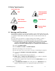
1-2 Safety Tag Information Dryer Safety Tags Hot! Read Operation and Installation Manual High Voltage Earth Ground Inside Enclosure PE Lifting Point Protected Earth Ground 1-3 Warnings and Precautions Our equipment is designed to provide safe and reliable operation when installed and operated within design specifications, following national and local safety codes. This may include, but is not limited to OSHA, NEC, CSA, SPI, and any other local, national and international regulations.
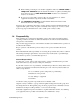
; When welding or brazing in or around this equipment, make sure VENTILATION is ADEQUATE. PROTECT adjacent materials from flame or sparks by shielding with sheet metal. An approved FIRE EXTINGUISHER should be close at hand and ready for use if needed. ; Do not restore power until you remove all tools, test equipment, etc., and the equipment and related components are fully reassembled. ; Only PROPERLY TRAINED personnel familiar with the information in this manual should work on this equipment.
Please read and use this manual as a guide to equipment safety. This manual contains safety warnings throughout, specific to each function and point of operation. Operator Responsibility The operator’s responsibility does not end with efficient production. The operator usually has the most daily contact with the equipment and intimately knows its capabilities and limitations.
• NEVER stand or sit where you could slip or stumble into the dryer while working on it. • DO NOT wear loose clothing or jewelry, which can be caught while working on a dryer. In addition, cover or tie back long hair. • Clean the dryer and surrounding area DAILY, and inspect the machine for loose, missing or broken parts. • Shut off power to the dryer when it is not in use. Turn the switch to the OFF position, or unplug it from the power source.
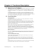
Chapter 2: Functional Description 2-1 Models Covered in This Manual This manual provides operation, installation, and maintenance instructions for 15, 30, and 60 cfm dehumidifying dryers. Model numbers are listed on the serial tag. Make sure you know the model and serial number of your equipment before contacting the manufacturer for parts or service.
2-3 Standard Features Mechanical Features • Dual desiccant beds • Electrically-actuated air valve • 13X Molecular Sieve • Single regenerative process blower • Drying temperature range of 180ºF to 250ºF (82ºC to 121ºC). • 2.5” hose connections Electrical Features • Process thermocouple to be connected to drying hopper air inlet.
2-4 Options Options marked with “*” indicate options that can be factory installed or retrofitted in the field. • * Process temperature up to 400ºF (204º C) or below 180ºF (82ºC), including aftercooler with dryer and silicone insulated delivery hose. Note: For below 180°F (82ºC), cooler needs to cool the air coming out of the desiccant tank prior to entering the process heater box. • * If the dryer is a central dry air generator, it will not have a process heater box.
Every effort has been made to incorporate these standards into the design of the drying system; however, it is the responsibility of the personnel operating and maintaining the equipment to familiarize themselves with the safety procedures and the proper use of any safety devices. Fail Safe Operation If a safety device or circuit should fail, the design must be such that the failure causes a “Safe” condition. As an example, a safety switch must be a normally open switch.
Chapter 3: Installation 3-1 Uncrating the Equipment Dehumidifying Dryers are shipped mounted on a skid, enclosed in a plastic wrapper, and contained in a cardboard box. 1. Pry the crating away from the skid. Note: Remove the nails holding the box to the skid and lift the box off carefully; avoiding staples in the 1’ x 4’ wood supports. Cut the steel banding. 2. Use a pry bar to remove the blocks securing the unit to the skid. 3. Lift unit from sides.
Figure 1: Suggested Lift Rigging for Cart Mount Dryers DO NOT USE DEW POINT ALARM HORN ALARM ALARM Silencer OFF ON PROCESS TEMPERATURE CONTROL POWER ON OFF USE FORK LIFT TRUCK Caution! Do not use a hoist to move or rig your Drying/Conveying System when it is mounted on a cart! Moving the unit with a hoist will cause it to become unstable and may cause damage to the equipment and/or injury to personnel! Figure 2: Suggested Lift Rigging for Cart Mounted Dryers Note: Note: Floor Mounted Dryers ca
Figure 3: Suggested Lift Rigging for Cart Mounted Dryers Mounting flange E E Diameter hole: F ON DEW POINT ALARM HORN ALARM ALARM Silencer Notes: Hopper mounting flanges on 0.75 and and 1.5 cu. ft. (20 & 40 liter) hoppers are supplied blank so the customer can drill to match existing machine throat. OFF PROCESS TEMPERATURE CONTROL POWER ON OFF 3.0 cu. ft. (80 liter) hoppers and larger are not supplied with a cast flange (as shown).
3-4 Setup Procedures This section provides the procedures necessary for configuring your portable drying/conveying system. Configuration of your unit includes checking for proper blower rotation and installing the optional aftercooler (on 60 cfm models). We recommend that you carry out these procedures in the order given here. Note: Before carrying out these procedures, install all equipment as described in this section.
NOTE: If the Aftercooler is used as a plasticizer trap, the water temperature of 50°F or lower is recommended. 3-5 Initial Start-up Pre-Startup Checks ; Check the process and return hoses for tight connections. ; Check all companion equipment, such as the drying hopper; verify that the loading system is ready for operation. ; Verify that all dryer electrical connections are tight. ; Verify that the thermocouple is properly installed at the hopper inlet. ; Verify temperature unit/scale.
Chapter 4: Operation 4-1 1. Start-up Turn on (energize) the disconnect switch in your power drop, and then turn on the one on the dryer. 2. Turn the system ON/OFF switch to ON to energize the display panel. 3. Close the slide gate at the bottom of the drying hopper. Make sure that the blowers turn in the right direction. 4. Fill the drying hopper with material. 5. Turn the dryer ON switch to START to start the dryer. The process blower starts. 6.
Process Air Temperature Controller Our dryers use a microprocessor-based PID temperature controller for maintaining process air temperature. The controller is a modular, self-contained unit you can remove from the mounting housing. All parameters except for the process air set point are factory set and adjusted; normally, no field adjustment to the internal controls is necessary.
Indicator Name Description PV Process Value Numeric LED During normal operation, the process value (PV) numeric LED indicator displays the process temperature at the To Process thermocouple. It also lists parameters during setup and error messages if any errors occur. Set Value Numeric LED During normal operation, the set value (SV) numeric LED indicator displays the process set point temperature selected for the dryer. The dryer then maintains this set point temperature.
Setting the Process Air Temperature When setting the process air temperature, consult with the resin manufacture for the recommended drying temperature. To change the process air temperature set point with the dryer running: • Press to raise the set point to the temperature you want. • Press to lower the set point to the temperature you want.
Adjustment Level Indicator Name Description Auto-Tune Mode (At) See Page 19 of Chapter 3 for instructions on how to Auto-Tune your dryer. Note: Dehumidifying Dryers Although the controller is calibrated at the factory, the manufacturer recommends that the unit be Auto-Tuned prior to dryer startup. Temperature Input Shift Mode (TnS) This setting is used to offset an error between the set point and the actual temperature.
Entering Operating Parameters to Select Modes To enter the display: 1. 2. Press the Mode Display key to view the Run/Stop & Alarm 1 Modes. and Press function On or Off. to set the higher or lower the values of the parameter or turn that The SV readout displays the different values for the parameter within a mode. 3. To switch modes within a level, press and hold the second. Level Display key for one (1) The PV readout will display the different parameters within each mode. 4.
Process Air Dew Point Display Optional The Process Air Dew Point meter indicates the current process air delivery moisture content. Standard dryers use a microprocessor-based controller for displaying dew point air temperature. The controller is a modular, self-contained unit removable from the mounting housing. All parameters are factory set and adjusted; normally, no field adjustment to the internal controls is necessary.
Redundant Safety Controller Display Optional The Redundant Safety Controller limits the process air temperature from exceeding the upper temperature range set by the E5CN Temperature Controller. Standard dryers use a microprocessor-based controller for limiting the process air temperature. The controller is a modular, self-contained unit removable from the mounting housing. All parameters are factory set and adjusted; normally, no field adjustment to the internal controls are necessary.
Entering Operating Parameters to Select Modes To enter the display: 1. Press both the Up and Down keys for three seconds from the home page. The word SEE will appear in the upper display and PAGE will appear in the lower display. 2. Press the Advance Key 3. Press the Up 4. Press the RESET Key at any time to return to the Home Page display. to move through the parameter prompts. or Down keys to change the parameter value. Figure 9: Setting List for Redundant Safety Controller (WATLOW), Part No.
4-3 System Operation Procedures Controller Operation (Without Optional Alarm Horn & Reset Button) 1. Turn the disconnect on the control panel to the ON position. Power is applied to the voltage line fuses, line side of the control power switch and the temperature controller. 2. Turn the control power switch to the ON position. Power is applied to the programmable relay and dew point controller. The valve will move to the start position as follows: a.
5. If the 1TCU (E5CN) controller faults, the optional redundant high temperature safety device opens, or the process heater safety switch opens, a heater fault is generated. “HIGH TEMP” is displayed on the relay screen. The alarm light is activated. The process heater, regen heater, and process/regen blower are turned off. Turn the OFF-ON-START switch to the START position to deactivate the alarm light and restart the dryer. If the fault condition still exists, the dryer will not restart. 6.
a. The valve motor rotates until the cam switch makes 2 transitions. b. If the cam switch does not make a transition within 10 seconds, a valve motor fault is generated. “VALVE MTR” is displayed on the relay screen, the alarm horn and light are activated. The valve motor, heaters, and blower shut off. Pressing the ALARM RESET pushbutton will deactivate the alarm horn and light. Cycle control power to restart the dryer.
Reset the motor overload and turn the Off-On-Start switch to the START position to restart the dryer. 7. The valve position limit switch enables the right bed heater and provides an input signal to the programmable relay when actuated by the cam lobe. Each heater is ON-OFF controlled by the OMRON E5C2 controller. 8. Upon completion of the HEAT portion of the regeneration sequence, the regen heaters are disabled by the programmable relay and the COOL time begins. 9.
Temperature Controller Alarm and/or Regen Heater Temp Switch and/or HIGH TEMP Process Heater Temp Switch and/or Redundant Temp Safety PROC BLWR Blower Overload VALVE MTR Valve Motor Time-Out HEAT COOL SYSTEM NORMAL No Alarms 4-4 35 30 Auto-Tuning the Dryer 1. For Auto-tuning, press the level key once. The AT screen will show with the setting OFF. 2. Press the UP arrow to change the setting to ON. 3. Press the level key again to go back to the Temperature Screen.
4. Turn the system ON/OFF switch to OFF. 5. If needed, empty the drying hopper. 6. For maintenance or a long term shutdown, open (de-energize) the electrical disconnects at the dryer and at the power drop.
Chapter 5: Maintenance 5-1 Preventative Maintenance Schedule The checklist below contains a list of items which should be inspected and/or replaced to keep your Portable Drying/Conveying System operating at peak efficiency. Perform each inspection at the regular intervals listed below.
5-2 Preventative Maintenance This section describes maintenance procedures which will increase the longevity and efficiency of your dehumidifying dryer. Perform them at the regular intervals listed on the dryer checklist on the previous page. Servicing Process Air Filters Caution! Operating the dryer without the process air filter installed voids your warranty! Filter cleaning is an important part of your dryer maintenance program.
Vacuuming Try vacuum-cleaning a soiled filter first. Vacuuming removes most large particles and surface contaminants, and may suffice for the first time you clean a filter. Use a commercialduty (recommended) or household vacuum cleaner. Vacuum the filter from the air intake (dirty) side only. Cleaning with Compressed Air Blow clean, dry compressed air up and down the pleats, blowing out the filter from the inside out. Remove loose dirt from the filter with compressed air or vacuum from the outside.
5-3 Corrective Maintenance This section provides you with the information necessary to correct or repair any issues which might appear during the normal operation of your dehumidifying dryer. Although we have listed how to perform these procedures, it is recommended that you call the Service Department to have any in-depth maintenance performed. Symptoms of Worn Desiccant The moisture absorption capacity of the desiccant used in your dehumidifying dryer degrades after an indefinite period of time.
Figure 11: Desiccant Bed Location and Disassembly Undo (4) 10-32 Button Head Screws using 1/8 Allen Wrench Desiccant Cap 1" Wide x 1/8" Thick Silicon Strip and Stick Gasket 13X Molecular Sieve 8x12 Beads Regeneration Heater Regeneration Thermocouple 16 Mesh 0.028 Diameter Wire Stainless Steel Screen (2) 4-40 screws Hi Temperature Snap Switch 1" Wide x 1/8" Thick High Temperature Gasket Caution! You should properly dispose of any discarded desiccant.
Figure 12: Required Desiccant Amounts Dryer model 15 cfm 30 cfm 60 cfm 8 x 12 bead Total Part no. lbs. 7.0 W00018051 15.75 37.5 Kg 3.25 7.25 17.0 Replacing the regeneration heaters Procedures (see figure 11). 1. Sketch the heater wiring configuration so you can properly re-wire the heater. 2. Remove the ceramic nuts and wires to the heater plate assembly being removed or replaced. 3.
Figure 13: Process Heater Location and Disassembly Undo (6) 10-32 Button Head Screws using 1/8 Allen Wrench 1" Wide x 1/8" Thick High Temperature Gasket (2) 4-40 screws Hi Temperature Snap Switch Procedures 1. Sketch the heater wiring configuration so you can properly re-wire the heater. 2. Remove the ceramic nuts and wires to the heater plate assembly being removed or replaced. 6.
Replacing/Cleaning the Cooling Coils WARNING! Hazardous electrical current present. Disconnect and lock out power before you replace heater elements! Figure 14: Cooling Coil Location and Disassembly 1" Wide x 1/8" Thick High Temperature Gasket Undo (4) 10-32 Button Head Screws using 1/8 Allen Wrench Use compressed air or a steam cleaner to blow the dust off or clean any oily residue on the coil. Water flow requirement: If used as an After-Cooler: 3 to 4 GPM @80F.
6 Troubleshooting 6-1 Introduction The utmost in safety precautions should be observed at all times when working on or around the machine and the electrical components. All normal trouble-shooting must be accomplished with the power off (or certified electrician should trouble shoot the unit) , line fuses removed, and with the machine tagged as out of service. The use of good quality test equipment cannot be over-emphasized when troubleshooting is indicated.
Alarm Message HIGH TEMP Cause Corrective Action The process temperature has exceeded the alarm set point. The high temperature snap switch of the process heater box has tripped. The high temperature snap switch on of the regeneration heater boxes has tripped PROC BLWR The process blower pressure switch did not detect enough pressure. Process blower overload has tripped. Process blower motor has failed. Lose contacts or wires.
Alarm Message Cause Corrective Action Dryer Status VALVE MTR The limit switch on the valve may not have been wired correctly. The valve has made enough rotations and the correct position of the valve was not detected. Limit switch may be out of position. Re-adjust the switch to make sure it trips when it is at the high position, and it does not touch the cam when it is at the low position. The switch is indicating the incorrect desiccant tank is in regeneration.
7 Appendix 7-1 Warranty Unless otherwise specified, this product includes a Standard ONE YEAR PARTS WARRANTY. Warranty Specifications The manufacturer hereby expressly warrants all equipment manufactured by it to be free from defects in workmanship and material when used under recommended conditions, as set forth in the operating manuals for such equipment.
applicable federal and state law, but not by the United Nations Convention on Contracts for the Sale of Goods. Customer Responsibilities Any sales, use, or other tax incident to the replacement of parts under this warranty is the responsibility of the purchaser. 7-2 Technical Specifications Annex B Information The following design information is provided for your reference: 1. No modifications are allowed to this equipment that could alter the CE compliance 2. Ambient temperature: 3.
24. The machine is not equipped with cable-less controls. 25. Color-coded (harmonized) power cord is sufficient for proper installation. Aftercooler Design Specifications Entering water temp. ºF 85ºF 50°F (If used as Plasticizer trap) 7-3 ºC 29ºC 10°C (If used as Plasticizer trap) Drawings and Diagrams Figure 15: Standard Model (180°F to 250°F) Air Flow Schematic Pressure switch, makes sure the blower is functioning correctly. Dryer valve High pressure peripheral regenerative blower.
Figure 16: High Heat Model (180°F to 400°F) Air Flow Schematic Pressure switch, makes sure the blower is functioning correctly. High pressure peripheral regenerative blower. Dryer valve 2” Hose Optional Return Air Cooler 2” Hose Utilizing -40F dew point air to regenerate and cool the desiccant. 2” Hose 13X Molecular Sieve 8x12 beads. Low watt density heaters, can operate safely with minimum air flow. Double wall constructed heater housing and desiccant container.
Figure 17: Low Heat Model (120°F to 250°F) Air Flow Schematic High pressure peripheral regenerative blower. Pressure switch, makes sure the blower is functioning correctly. Dryer valve 2” Hose Utilizing -40F dew point air to regenerate and cool the desiccant. Process / Regeneration Air Filter 13X Molecular Sieve 8x12 beads. Low watt density heaters, can operate safely with minimum air flow. Double wall constructed heater housing and desiccant container.
7-4 Spare Parts List 575V 60 HZ 3PH 60CFM 60CFM 460V 3PH 400V 50 HZ 3PH 60CFM 60CFM 230V 3PH 220V 50 HZ 3PH 60CFM 60CFM 208V 3PH 575V 60 HZ 3PH 30CFM 30CFM 460V 3PH 400V 50 HZ 3PH 30CFM 30CFM 230V 3PH 30CFM 220V 50 HZ 3PH 30CFM 208V 3PH 3 575V 60 HZ 3PH 15CFM 15CFM 460V 3PH 15CFM 3 3 3 3 3 3 3 3 3 3 3 3 3 3 3 3 3 3 3 3 3 3 3 3 3 3 3 3 3 3 3 3 3 3 3 3 3 3 3 3 3 3 3 3 3 3 3 3 3 3 3 3 2 2 2 2 2 1 1 1 7Appendix 2 1 1 1 1 1 1 1 1 1 1 1 1 1 1 4.
LEVEL 2 ( Mechanical Components ) PART # SIZE Description A0548621 Ceramic Cap for the End of Heater Elements A0566478 750 Watts Heater element 208/220 Volts A0566479 750 Watts Heater element 230 Volts A0566480 750 Watts Heater element 400 Volts A0566481 750 Watts Heater element 460 Volts A0566482 750 Watts Heater element 575 Volts A0566483 1250 Watts Heater Element 208/220 Volts A0566484 1250 Watts Heater Element 230 Volts A0566485 1250 Watts Heater Element 400 Volts A0566486 1250 Watts Heater Element 460
7-5 Returned Material Policy Credit Returns Prior to the return of any material authorization must be given by the manufacturer. A RMA number will be assigned for the equipment to be returned. Reason for requesting the return must be given. ALL returned material purchased from the manufacturer returned is subject to 15% ($75.00 minimum) restocking charge. ALL returns are to be shipped prepaid. The invoice number and date or purchase order number and date must be supplied.
7-7 Technical Assistance Parts Department Call toll-free 7am–5pm CST [800] 423-3183 or call [630] 595-1060, Fax [630] 475-7005 The ACS Customer Service Group will provide your company with genuine OEM quality parts manufactured to engineering design specifications, which will maximize your equipment’s performance and efficiency. To assist in expediting your phone or fax order, please have the model and serial number of your unit when you contact us.