SF Series Additive Feeders Part Number: 882.00274.00 Bulletin Number: BF2-605 Effective: 10/31/05 Write Down Your Serial Numbers Here For Future Reference: _________________________ _________________________ _________________________ _________________________ _________________________ _________________________ We are committed to a continuing program of product improvement. Specifications, appearance, and dimensions described in this manual are subject to change without notice. DCN No.
Please note that our address and phone information has changed. Please reference this page for updated contact information. These manuals are obsolete and are provided only for their technical information, data and capacities. Portions of these manuals detailing procedures or precautions in the operation, inspection, maintenance and repair of the products may be inadequate, inaccurate, and/or incomplete and shouldn’t be relied upon.
Shipping Information Unpacking and Inspection You should inspect your additive feeder for possible shipping damage. Thoroughly check the equipment for any damage that might have occurred in transit, such as broken or loose wiring and components, loose hardware and mounting screws, etc. In the Event of Shipping Damage According to the contract terms and conditions of the Carrier, the responsibility of the Shipper ends at the time and place of shipment.
Table of Contents CHAPTER 1: SAFETY .................................................................V 1-1 1-2 1-3 How to Use This Manual ............................................................................................. v Safety Symbols Used in this Manual ..................................................................... v Warnings and Precautions ......................................................................................... vi Responsibility .....................................
CHAPTER 5: MAINTENANCE ................................................... 32 5-1 5-2 5-3 Preventative Maintenance Schedule......................................................................... 32 Preventative Maintenance......................................................................................... 33 Material Cleanout/Changeover............................................................................33 Corrective Maintenance ................................................................
Chapter 1: Safety 1-1 How to Use This Manual Use this manual as a guide and reference for installing, operating, and maintaining your additive feeder. The purpose is to assist you in applying efficient, proven techniques that enhance equipment productivity. This manual covers only light corrective maintenance. No other maintenance should be undertaken without first contacting a service engineer. The Functional Description section outlines models covered, standard features, and safety features.
1-2 Warnings and Precautions Our equipment is designed to provide safe and reliable operation when installed and operated within design specifications, following national and local safety codes. This may include, but is not limited to OSHA, NEC, CSA, SPI, and any other local, national and international regulations.
1-3 Responsibility These machines are constructed for maximum operator safety when used under standard operating conditions and when recommended instructions are followed in the maintenance and operation of the machine. All personnel engaged in the use of the machine should become familiar with its operation as described in this manual. Proper operation of the machine promotes safety for the operator and all workers in its vicinity.
Operator Responsibility The operator’s responsibility does not end with efficient production. The operator usually has the most daily contact with the equipment and intimately knows its capabilities and limitations. Plant and personnel safety is sometimes forgotten in the desire to meet incentive rates, or through a casual attitude toward machinery formed over a period of months or years. Your employer probably has established a set of safety rules in your workplace.
• Clean the feeder and surrounding area DAILY, and inspect the machine for loose, missing or broken parts. • Shut off power to the feeder when it is not in use. Turn the switch to the OFF position, or unplug it from the power source. Maintenance Responsibility Proper maintenance is essential to safety. If you are a maintenance worker, you must make safety a priority to effectively repair and maintain equipment.
Chapter 2: Functional Description 2-1 Models Covered in This Manual This manual provides operation, installation, and maintenance instructions for 1 and 2 component additive feeders. Model numbers are listed on the serial tag. Make sure you know the model and serial number of your equipment before contacting the manufacturer for parts or service. Our additive feeders are designed to precisely feed up to two components before being used in the injection molding, blow molding or extrusion processes.
Motor Assembly • Quick release swing-away motor mount speeds auger/motor changes and cleanout • Permanently lubricated • Replaceable motor brushes Electrical Features Motor Assembly • Continuous service fractional horsepower DC motor. • Hall Effect sensor transmits RPM to microprocessor control • 115/1/60 supply voltage Controller Features • Closed-loop control constantly monitors feedback from the auger motor RPM sensor for high accuracy and repeatability.
Dual Setpoint Control • Used with multiple feeder installations where one feeder is feeding colored regrind and another is feeding straight color. A low level monitor senses when the supply of colored regrind is depleted and alters the feed rate of the pure color feeder to maintain precise color quality control automatically.
2-6 Safety Devices and Interlocks This section includes information on safety devices and procedures that are inherent to the additive feeder. This manual is not intended to supersede or alter safety standards established by the user of this equipment. Instead, the material contained in this section is recommended to supplement these procedures in order to provide a safer working environment.
Safety Device Lock-Outs Some safety devices disconnect electrical energy from a circuit. The safety devices that are used on these additive feeders are primarily concerned with electrical power disconnection and the disabling of moving parts that may need to be accessed during the normal operation of the machine. Some of the safety devices utilize a manual activator. This is the method of initiating the safety lock out. This may be in the form of a plug, lever or a handle.
Chapter 3: Installation 3-1 Uncrating the Equipment Additive feeders are shipped mounted on a skid, enclosed in a plastic wrapper, and contained in a cardboard box. 1. Pry the crating away from the skid. Note: Remove the nails holding the box to the skid and lift the box off carefully; avoiding staples in the 1’ x 4’ wood supports. Cut the steel banding. 2. Use a pry bar to remove the blocks securing the unit to the skid. 3. Lift unit from sides.
3-3 Electrical Connections When making electrical connections to your additive feeder, ensure that you take into consideration and make arrangements for the following: • A qualified electrician should make all electrical connections. • Fulfill all national, state, and local safety and electrical code requirements. • The serial tag lists voltage, phase, and amp draw information: • Line voltage must be within plus or minus ten percent (±10%) of the voltage listed on the serial tag, or damage may occur.
3-4 Setup Procedures This section provides the procedures necessary for configuring your additive feeder. Configuration of your additive feeder includes determining the desired feed rate and calibrating the additive feeder. We recommend that you carry out these procedures in the order given here. Note: Before carrying out these procedures, install all equipment as described in this section.
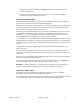
Figure 1: Conversion Chart Multiply Ounces per Second Grams Ounces Seconds By To obtain Pounds per Hour Ounces Pounds Hours 225 0.035 0.0625 0.
Calibration Procedure This procedure allows the operator to precisely adjust additive feed rates. Caution! Never put hands or tools in or near the auger assembly when power is connected. Do not wear gloves or loose clothing during calibration. The auger is exposed when the calibration or cleanout hatches are open. Equipment Needed: • Scale • Sample container • Timer- stopwatch, watch/clock w/second hand Procedure 1. Close cleanout and calibration hatches. 2. Fill the additive supply hopper. 3.
Examples: This example shows how to extrapolate a desired feed rate of 3 lbs./hr., based on the feed rates of 3 trial rpm settings. Observed Feed Rates Sample 1 = 2 pounds per hour @ 20 rpm Sample 2 = 4 pounds per hour @ 40 rpm Sample 3 = 6 pounds per hour @ 60 rpm In this example, a feed rate of 3 lbs./hr. would be about 30 rpm.
3-5 Initial Start-up Pre-Startup Checks ; Are all the electrical connections correct, secure and to code? ; Is the auger insert locked in place? ; Are the motor and auger properly coupled and the motor mount locked in place? ; Are the cleanout and calibration hatches shut and secured? ; Are all tools, hardware, etc.
Chapter 4: Operation 4-1 Start-up 1. Turn the power switch ON. 2. Set the desired feed rate on the RPM display using the up or down arrows. 3. Flip the motor switch to AUTO. If the additive feeder is installed correcly, it should begin operation at the desired RPM when the processing machine screw is in operation. 4-2 Controller Description and Operation Identifying Control Panel Indicator Lights and Switches on the Controller Switches Power Switch. This switch turns the control ON and OFF. Motor Switch.
Timer/Counter Control Operation (Injection Molding Applications) The Timer/Counter control is designed for use with cyclical processes like injection molding and features a timer and counter module. It also acts as a cycle override safety timer. Timer Module This feature of the controller assists in calibration of the additive feeder (See Page 20 for specific calibration instructions.). Procedure 1.
Timer/Elapsed Timer Control (Extrusion & Blow Molding Applications) The Timer/Elapsed Timer control is designed for use with continuous processes like extrusion and blow molding and features a timer and elapsed time module. Timer Module This feature of the controller assists in calibration of the additive feeder (See Page 20 for specific calibration instructions.). 1. Set the timer to the desired calibration period, using the round timer keys (see the timer information sheet for additional information.) 2.
Dual Setpoint Control Operation (2 Component Applications) A dual setpoint control operation is offered on the dual auger/hopper additive feeder. Typically, one feeder hopper is filled with additive and the other (with a proximity switch) is filled with regrind. This option allows for the accurate addition of additive and provides a consistant addition of regrind into the process stream. Regrind Feeder with Proximity Switch The regrind feeder feeds regrind into the process stream.
Extruder Tracking Control The extruder tracking control option allows the additive feeder’s auger (follower) to turn in a precise ratio to the speed of your extruder screw (master). The speed control on the feeder can be set for any feed ratio from 1% to 999.9%. The extruder tracking control detects the speed of the extruder screw and causes the feeder screw to rotate at the desired RPM. In effect, the extruder tracking control acts as an automatic speed control.
6. Determine the desired additive feeder setpoint (% of extruder (master) screw RPM). To determine this, you must know: • Total extruder feedrate (lbs./hr.). • The RPM of the extruder screw at that feedrate. • The letdown ratio of the additive (% or :). • The additive feedrate required at that letdown ratio (total feedrate X letdown ratio). • The additive feedrate RPM needed to achieve this feedrate (as determined by the calibration procedure).
Field Control Programming The standard additive feeder controller has the ability to display feed rates in units other than the factory set auger RPM display. With the proper programming, the feeder can display pounds/hour, grams/minute, etc. The non-volatile memory retains the program if the power is interrupted. Note: The field programmer should have a basic understanding of programmable motor controls before attempting to reprogram the display. Page 32 lists the factory default settings.
Programming Mode The motor will stop when in Programming mode. 1. Make sure DIP switches 1 through 4 and 7 and 8 are OFF. 2. Flip switch 7 to ON. 3. The display should read PROG. 4. Follow the instructions given below to view and/or edit any of the variables. Viewing or Changing Displayed Decimal Place/Rate or Time Mode Select 1. Make sure you are in Programming Mode, then flip DIP switch 4, RATE-TME MODE/PROGRAM DECIMAL PLACE, ON. 2.
Viewing or Changing the Program Minimum Setting 1. Enter the programming mode, then flip DIP switch 2, Program Minimum Setting, to ON. 2. The current value for the lower limit FACTORY SETTING = 0 will appear in the LED display. 3. Use the Up or Down buttons to change the lower limit, as desired. 4. When finished, flip DIP switch 2 to OFF. 5. The display should read PROG. Viewing or Changing the Program Maximum Setting 1. Enter the programming mode, then flip DIP switch 3, PROGRAM MAXIMUM SETTING to ON. 2.
Additive Feeder Control Factory Defaults WARNING! This procedure involves resetting a DIP switch within a live electrical enclosure. Only persons with the proper knowledge of and respect for working on energized electrical devices should attempt this procedure. Use extreme caution! Note: Set the decimal point with DIP switch 4 first to avoid confusion when keying in the presets; for example, 300 and 30.0.
Chapter 5: Maintenance 5-1 Preventative Maintenance Schedule The checklist below contains a list of items which should be inspected and/or replaced to keep your Additive Feeder operating at peak efficiency. Perform each inspection at the regular intervals listed below. System model # Every week Serial # Date/ By Date/ By Date/ By Date/ By Date/ By Date/ By Date/ By Date/ By Date/ By Date/ By Date/ By Date/ By Date/ By Inspect auger, sleeve and hopper throat. Clean if dirty.
5-2 Preventative Maintenance This section describes maintenance procedures which will increase the longevity and efficiency of your additive feeder. Perform them at the regular intervals listed on the checklist on the previous page. Material Cleanout/Changeover Caution! Never put hands or tools in or near the auger assembly when power is connected! Do not wear gloves or loose clothing when working near the auger assembly! 1.
5-3 Corrective Maintenance This section provides you with the information necessary to correct or repair any issues which might appear during the normal operation of your additive feeder. Although we have listed how to perform these procedures, it is recommended that you call the Service Department to have any in-depth maintenance performed. Auger Assembly Changeover Our additive feeder auger assemblies may be removed and installed without tools. All auger sizes are interchangeable.
Motor Brush Replacement The two (2) motor brushes should be replaced when they are worn down to less than 1 inch in length. Replacement brushes are “pre-worn” by the manufacturer and require no break-in period. Caution! Disconnect power to the Additive Feeder before changing the motor brushes. 1. Remove a brush cap screw near the back of the motor. Caution! The motor brushes are spring loaded. Use care to avoid eye injury when removing the cap screw. Wear safety glasses when performing this procedure.
Chapter 6: Troubleshooting 6-1 Introduction The utmost in safety precautions should be observed at all times when working on or around the machine and the electrical components. All normal trouble-shooting must be accomplished with the power off, line fuses removed, and with the machine tagged as out of service. The use of good quality test equipment cannot be over-emphasized when troubleshooting is indicated.
Problem Possible cause Field contact jumper (J1) has not been removed. AUTO MODE. Motor will not stop. Motor runs only at maximum speed. Motor speed not constant. Additive is contaminated by color from previous run. Field contact to the processing machine has failed. Motor switch has failed. Field contact to process machine missing or loose. Control relay has failed. Motor control has failed. Optional timer set incorrectly. Optional timer has failed. Signal from motor speed sensor missing.
Chapter 7: Appendix 7-1 Warranty The manufacturer warrants all equipment manufactured by it to be free from defects in workmanship and material when used under recommended conditions. The company’s obligation is limited to repair or replace FOB the factory any parts that are returned prepaid within one year of equipment shipment to the original purchaser, and which, in the company’s opinion, are defective. Any replacement part assumes the unused portion of this warranty.
7-2 Optional Components The following is a list of options which your Additive Feeder may have been equipped with: Special Voltage • 230/1/50 VAC Timer/Counter Control • Designed for use with cycled processes like injection molding • Cycle timer can be set to limit additive feeder cycle to avoid feeding straight color if a resin supply problem occurs in conjunction with a processing machine control relay failure.
7-3 Technical Specifications Annex B Information The following design information is provided for your reference: 1. No modifications are allowed to this equipment that could alter the CE compliance 2. Ambient temperature: 0 degrees Celsius – Maximum (104 degrees Fahrenheit) 3. Humidity range: 50% relative humidity 4. Altitude: Sea level 5. Environment: Clean, dust-free and non-explosive 6. Radiation: None 7. Vibration: Minimal, i.e. machine mounting 8.
16. Functional identification 17. Additive Feeder is equipped with a CE mark 18. Additive Feeder is supplied with an operating manual in the language of the destination country. 19. Cable support may be required for power cord, depending on final installation. 20. No one is required to be in the interior of the electrical enclosure during the normal operation of the unit. Only skilled electricians should be inside the enclosure for maintenance. 21.
CONTROLS MOUNTING FLANGE ADDITIVE FEEDER ADDITIVE FEEDER 4" 7" SET POINT SET POINT 91 2" POWER ON 9 1 2" MOTOR MOTOR ON AUTO POWER OFF OFF MAN ON MOTOR MOTOR ON AUTO OFF OFF MAN 4" 7" 61 4" 61 4" STANDARD STANDARD WITH OPTIONS 27 34" 12" 183 4" 6" 3114" Additive Feeder Type 1 Component 2 Component Hopper capacity Electrical supply 1.0 Cu. Ft. (2) 1.0 Cu. Ft. 115-1-60 115-1-60 Amp draw 1.3 2.5 Shipping weight 50 lbs. 90 lbs.
SET POINT SET POINT POWER ON MOTOR MOTOR ON POWER OFF MOTOR MOTOR ON ON AUTO OFF OFF MAN SET POINT #1 SET POINT #1 (HIGH LEVEL) SET POINT (HIGH LEVEL) SET POINT SET POINT # 1 SET POINT # 1 (LOW LEVEL) MOTOR ON SET POINT #2 (LOW LEVEL) SET POINT SET POINT #2 SET POINT POWER SET POINT # 2 ON SET POINT # 2 OFF POWER ON OFF MOTOR MOTOR ON AUTO SET POINT # 1 MOTOR OFF AUTO MAN OFF MAN SET POINT # 2 Additive Feeders Chapter 7: Appendix 43 of 50
7-5 Spare Parts List Figure 8: Exploded Assembly Drawing Figure 9: Parts List Detail # 1 1 2 2 2 3 4 5 6 7 8 9 10 10 11 12 13 14 15 16 17 18 Part number A0541207 A0541208 A0541225 A0541226 A0541227 A0541286 A0541285 A0101190 A0541206 W0012471 W00052210 A0541201 A0541202 A0541208 A0541205 A0069242 W00001948 A0069203 A0069458 A0541216 A0541215 A0540904 Additive Feeders Part/assembly description Supply Hopper, 1.0 Cubic Foot Supply Hopper, 2.
Detail # 19 20 21 22 Part number W00052550 A0069218 A0069549 A0541279 Knob, Knurled Stop Nut, 5/16-18 Flat Washer, 3/8" Screw, 5/16-18 x 4½" Part/assembly description 23 24 25 25 25 25 25 25 26 26 26 26 Assy. Assy. Assy. Assy. Assy. Assy.
Figure 10: One Component Control Enclosure Parts Identification ADDITIVE FEEDER 20 19 OR 41 6 11 5 SET POINT 18 16 17 4 9 8 7 POWER 9 MOTOR ON 3 MOTOR ON (SEE DETAIL A) OFF 10 OR 52 2 1 R Whitlock 50 14 15 12 13 TO ENCLOSURE ON MOTOR FUSE HOLDER 115V POWER ADDITIVE FEEDER 32 SET POINT A0541236 DETAIL A 36 POWER 33 LEFT SIDE VIEW 31 OR 35 30 ON 230V OPTION 50 1 A0544795 ASSY,TRANSFORMER,CNTL,230:115 EXTRUDER TRACKING OPTION (SEE NOTE #2) 41 40 1 1 A0541610 A0541673
Figure 11: Two Component Control Enclosure Parts Identification ADDITIVE FEEDER SET POINT #1 20 10 (HIGH LEVEL) SET POINT SET POINT # 1 41 OR 19 6 5 17 SET POINT #2 18 10 11 7 8 POWER 9 4 MOTOR MOTOR ON ON AUTO SEE DETAIL A OFF OFF 2 MAN 1 10 50 R Whitlock 15 14 TO ENCLOSURE ON MOTOR 12 13 PROX SWITCH (ITEM #22) FUSE HOLDER 115V POWER ADDITIVE FEEDER SET POINT #1 (HIGH LEVEL) 33 SET POINT A0541237 SET POINT #2 SET POINT # 1 DETAIL A (LOW LEVEL) LEFT SIDE VIEW MOTO
7-6 Returned Material Policy Credit Returns Prior to the return of any material authorization must be given by the manufacturer. A RMA number will be assigned for the equipment to be returned. Reason for requesting the return must be given. ALL returned material purchased from the manufacturer returned is subject to 15% ($75.00 minimum) restocking charge. ALL returns are to be shipped prepaid. The invoice number and date or purchase order number and date must be supplied.
7-8 Additive Feeder Identification (Serial Number) Tag (Located on back of Additive Feeder) Company Logo XX-X Series Additive Feeder Model Number XX-X Max Blend Capacity 318 KG/HR 220V Serial Number 060701R 1Ǿ Date of Manufacture 06/2004 4.5A Over-current Protection Device (s) 4.5A Total Frequency 50/60Hz Compressed air supply 4.
Worksheet for Charting Feed Rates Material ________________________________ Auger size _______________________________ Feed rate unit of measure _________________ Trial #1 rpm _____________ Feed rate _______________ Trial #2 rpm _____________ Feed rate _______________ 80 70 60 Auger 50 RPM setting 40 30 20 10 0 0 ____ ____ ____ ____ ____ ____ ____ ____ Observed feed rates (lbs./hr., oz./min., etc.