
Installation Guide


Prepare the Site (cont.)
Carefully measure your fixture before determining enclosure size. Some shimming between the stud frame
and the fixture may be required. Dimensions given in the Roughing-In section are crucial for proper
installation. Construct the framing and plumbing accurately.
NOTE: When installed over drywall, plaster, or other water-resistant wall material, the wall flanges should
be covered with a finish molding. This molding is not provided with the product.
IMPORTANT! Unless otherwise specified, floor support under the whirlpool must provide for a minimum
of 80 lbs/square foot (390 kg/square meter) loading.
If installing a unit with wall surrounds to a masonry wall, make provisions for plumbing connections. For
the plumbing end wall, construct a separate frame wall a minimum of 6″ (15.2 cm) from the masonry wall.
For the other walls, use 2x2 or equivalent furring strips to simulate stud locations.
If installing a whirlpool-only unit to a masonry wall, make provisions for plumbing connections and finish
wall installation. A 2x2 or equivalent furring strip around the inside edge of the whirlpool may be used to
secure the whirlpool in place. Locate the furring strip at the height needed for the attachment clips or roofing
nails, whichever will be used.
If installing this unit with a shower door, refer to the shower door manufacturer’s instructions for any special
framing considerations. It may be appropriate to add studs for pivot shower door support.
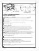
2. Framing Construction
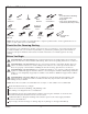
This whirlpool with apron must be attached to the walls on three sides. Attach the whirlpool using the
supplied attachment clips or large-headed roofing nails. The attachment clips or nails limit the freedom of
movement for the sides and ends of the whirlpool. The wall attachment is not intended to be load bearing.
Subflooring must be installed. The whirlpool must be positioned to allow clearance for drainage through the
floor joists or slab and to allow convenient plumbing installation. Studs must be positioned roughly where
shown for attaching clips or fastening the nailing-in-flange. Other stud locations are optional but must meet
the load-bearing requirements of local building codes. Studs must also allow for the installation of the
plumbing fixtures and any shower door. Locate the shower door stud as required by the manufacturer.
NOTE: Refer to the Roughing-In section for dimensions.
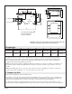
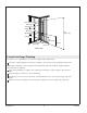
Framing Installation
For installations with wall surrounds, provide support for the vertical wall flanges at 33-1/4″ (84.5
cm).
Ensure that the framing is plumb and square to within 1/8″ (3 mm). Shimming may be required.
Construct 2x4 framing for your particular installation according to the Roughing-In section.
Construct an access panel to allow access for servicing the faucets and drain.
For installations with wall surrounds, cover or seal any loose material.
NOTE: For units with wall surrounds, the installation of accessories that require backing or support is not
recommended. Such installations could void the warranty.
For an installations using a shower door, refer to the shower door manufacturer’s instructions for
any special framing considerations.
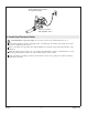
Flooring Construction
NOTE: The Roughing-In section indicates the location of the whirlpool basin drain. The overflow drain
location is not shown. Provide a cutout in the floor large enough to fit the drain assembly selected for
your installation.
Cut a hole for the drain in the floor.
1032207-2-C 6 Sterling