Upright Hot Oil Temperature Control Units Part Number: 682.88107.00 Bulletin Number: SC1-660.3 Effective: 10/22/2009 Write Down Your Serial Numbers Here For Future Reference: _________________________ _________________________ _________________________ _________________________ _________________________ _________________________ We are committed to a continuing program of product improvement. Specifications, appearance, and dimensions described in this manual are subject to change without notice.
Shipping Info Unpacking and Inspection You should inspect your portable hot oil tcu for possible shipping damage. Thoroughly check the equipment for any damage that might have occurred in transit, such as broken or loose wiring and components, loose hardware and mounting screws, etc. In the Event of Shipping Damage According to the contract terms and conditions of the Carrier, the responsibility of the Shipper ends at the time and place of shipment.
Table of Contents CHAPTER 1: SAFETY ................................................................ 5 1-1 1-2 1-3 How to Use This Manual ............................................................................................. 5 Safety Symbols Used in this Manual .....................................................................5 Warnings and Precautions .......................................................................................... 6 Responsibility ......................................
-1 4-2 4-3 4-4 Start-up...................................................................................................................... 24 Controller Description & Operation............................................................................ 24 Identifying Control Panel Switches ......................................................................25 Identifying System Status Board Indicators.........................................................26 Status Indicator Lights ................
Chapter 1: Safety 1-1 How to Use This Manual Use this manual as a guide and reference for installing, operating, and maintaining your portable hot oil temperature control unit (TCU). The purpose is to assist you in applying efficient, proven techniques that enhance equipment productivity. This manual covers only light corrective maintenance. No other maintenance should be undertaken without first contacting a service engineer.
1-2 Warnings and Precautions Our equipment is designed to provide safe and reliable operation when installed and operated within design specifications, following national and local safety codes. This may include, but is not limited to OSHA, NEC, CSA, SPI, and any other local, national and international regulations.
1-3 Responsibility These machines are constructed for maximum operator safety when used under standard operating conditions and when recommended instructions are followed in the maintenance and operation of the machine. All personnel engaged in the use of the machine should become familiar with its operation as described in this manual. Proper operation of the machine promotes safety for the operator and all workers in its vicinity.
Operator Responsibility The operator’s responsibility does not end with efficient production. The operator usually has the most daily contact with the equipment and intimately knows its capabilities and limitations. Plant and personnel safety is sometimes forgotten in the desire to meet incentive rates, or through a casual attitude toward machinery formed over a period of months or years. Your employer probably has established a set of safety rules in your workplace.
• Clean the tcu and surrounding area DAILY, and inspect the machine for loose, missing or broken parts. • Shut off power to the tcu when it is not in use. Turn the switch to the OFF position, or unplug it from the power source. Maintenance Responsibility Proper maintenance is essential to safety. If you are a maintenance worker, you must make safety a priority to effectively repair and maintain equipment.
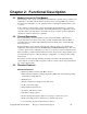
Chapter 2: Functional Description 2-1 Models Covered in This Manual This manual provides operation, installation, and maintenance instructions for portable hot oil temperature control units. Model numbers are listed on the serial tag. Make sure you know the model and serial number of your equipment before contacting the manufacturer for parts or service.
Electrical Features • Non-fused lockable rotary disconnect • Branch circuit fusing • NEMA 12 electrical enclosure • UL listed subpanel Controller Features • M2B+ microprocessor controller with fuzzy logic; includes diagnostic features with indicator and warning status lights • System status graphic display • Low level alarm for reservoir • Audible alarm • 5 year warranty on controller 2-4 Options Options marked with “*” indicate options that can be factory installed or retrofitted in the field.
2-5 Feature Descriptions Immersion Heaters The fluid is heated by the specially designed three-phase low watt density electrical immersion heater, and regulated by the controller. The standard heater has a steel sheath for low watt density and good heat transfer. These models can be supplied with 6, 12, 18, or 24 kW low watt density immersion heaters, depending upon the heating needs of the process.
Connection Lines Connections for TO PROCESS and FROM PROCESS lines are 1" NPT (25.4 mm). Water connections for COOLING WATER SUPPLY and COOLING WATER DRAIN are ¾” NPT (19.1 mm); see Section 3-4 on Page 20 for more information. The customer is responsible for conversions to metric standards. The manufacturer stocks many lengths of flexible metal hose; the part number is 572-16969. State the length of hose you want when ordering.
Air Purge Upon initial start-up and mold/process change-out, you’ll need to purge all air and water from the system. The Upright unit has appropriate valving to ensure complete purging. Procedures are covered in Section 3-5 on Page 23. WARNING! Failure to purge the system of air before heating may result in serious injury or critical system and equipment damage. Make sure you properly purge the system of air before starting the heater cycle.
Cooling (Optional) The manufacturer-designed shell and tube heat exchanger is provided as optional equipment in this unit. The design features U-tube construction and copper-nickel tubes for durability and optimal heat transfer. The modular construction (unique to our units) allows the tube bundle to be easily removed for periodic cleaning.
Fail Safe Operation If a safety device or circuit should fail, the design must be such that the failure causes a “Safe” condition. As an example, a safety switch must be a normally open switch. The switch must be held closed with the device it is to protect. If the switch fails, it will go to the open condition, tripping out the safety circuit. At no time should the safety device fail and allow the operation to continue.
Chapter 3: Installation 3-1 Uncrating the Equipment Portable hot oil temperature control units are shipped mounted on a skid, enclosed in a plastic wrapper, and contained in a cardboard box. 1. Pry the crating away from the skid. Note: Remove the nails holding the box to the skid and lift the box off carefully; avoiding staples in the 1’ x 4’ wood supports. Cut the steel banding. 2. Use a pry bar to remove the blocks securing the unit to the skid. 3. Lift unit from sides.
3-3 Electrical Connections These units are designed for three-phase voltage operation. Refer to the unit nameplate for proper voltage and amperage requirements, and make sure your electrical service conforms. Check the unit nameplate for correct voltage and amperage before making electrical connections! Caution! 1. Provide a correctly sized and protected power supply to the unit. 2.
3-4 Setup Procedures This section provides the procedures necessary for configuring your portable hot oil temperature control unit. Configuration of your TCU includes connecting cooling, process and vent piping. We recommend that you carry out these procedures in the order given here. Note: Before carrying out these procedures, install all equipment as described in this section. Connecting Piping Make sure that all external piping is properly sized to reduce external pressure drop as much as possible.
Connecting Process Piping When connecting process piping, ensure that the Cautions listed below are observed and followed: Caution! • Hoses, valves and other components in your process must be able to withstand Upright unit maximum temperatures and pressures. • Maximum temperatures and pressures are listed on the unit nameplate. • Carefully inspect all components before installation. • If in doubt about component suitability, obtain factory components.
Figure 1: Upright Unit Piping Setup Connect the TO PROCESS hookup to the entrance of the process and the FROM PROCESS hookup to the exit of the process. Connect the COOLING WATER SUPPLY to your plant water supply. Connect the COOLING WATER DRAIN line to an open drain, or to the return line of your central water system. If returning to a central water system, use a condensate/return tank to avoid a standing water column on the heat exchanger drain line.
3-5 Initial Start-up Starting the Hot Oil TCU Before you begin your heating process, perform the following startup procedures. Doing so ensures that all air is vented from the system to prevent fluid degradation and damage to the heater. 1. Add recommended heat transfer fluid to the reservoir tank until the level is near the top of the sight glass. 2. If so equipped, open the manual vent valve on the back of the unit. 3.
The Upright unit is now ready for use. All that is now required, is to select a process set point on the controller. Note: If all traces of water are not removed from the system, severe cavitation may occur at elevated temperatures. Indications are a rough-sounding pump, fluctuating or dropping pressure, or a rapidly rising fluid level in the expansion tank. Repeat Step 3 if this occurs.
Chapter 4: Operation 4-1 Start-up 1. Push the PUMP START button to start the pump. 2. When the unit has built at least five (5) psi (34.5 kPa) of pressure, wait two (2) minutes, then select a set point of 100°F (38ºC) and switch the unit into AUTO mode. As the oil warms up, viscosity decreases and pressure falls. 3. Four to six inches (4” to 6” / 10 cm to 15 cm) of fluid should be visible in the sight glass. 4. Select a process set point on the controller.
Identifying Control Panel Switches This section lists the descriptions and functions of the control panel switches. These switches control the operation of the unit. Figure 4: Control Panel Switches Pump Start. Press the START button to start the pump in the normal forward direction. Pump Stop. Press the STOP button to stop the pump and de-energize the controller. Caution! Always press the Pump Stop button and allow the pump to come to a complete stop before pressing the Pump Reverse button.
Mode Select. With the pump running, you can select the AUTO position or the Maintained (manual cooling) position with the Mode Select switch. Select AUTO mode to energize the controller, permitting it to monitor and control the process. The switch automatically returns to the Center Default position when in AUTO mode. The switch stays in the Maintained position in Manual Cooling mode. Caution! Always let the pump run for at least one (1) minute before switching to AUTO mode.
Status Indicator Lights Pump Reverse Indicator Light. The Pump Reverse indicator light illuminates when the unit pump runs in reverse. Pump Forward Indicator Light. The Pump Forward indicator light illuminates when the unit pump runs in the normal forward direction. This indicator typically illuminates continuously during normal operation. Heater On Indicator Light. The Heater On indicator illuminates when the heater energizes. Cool Solenoid Indicator Light.
High Level Indicator Light (Optional). The High Level indicator light illuminates when the heat transfer fluid level in the reservoir tank is too high. Carefully remove just enough fluid so this indicator light shuts off. Low Level Indicator Light. The Low Level indicator light illuminates when the heat transfer fluid level in the system is too low. This is an alarm condition, so the audible alarm activates to notify you of the low fluid level fault, and the controller outputs are disabled.
When fluid temperature dips below 120ºF (49ºC), press the PUMP STOP button to turn off the unit.
Chapter 5: Maintenance 5-1 Maintenance Schedule The checklist below contains a list of items which should be inspected and/or replaced to keep your Portable Hot Oil TCU operating at peak efficiency. Perform each inspection at the regular intervals listed below. System model # Every week Serial # Date/ By Date/ By Date/ By Date/ By Date/ By Date/ By Date/ By Date/ By Date/ By Date/ By Date/ By Date/ By Date/ By Check fluid level.
5-2 Preventative Maintenance WARNING! Make sure that your maintenance technicians comply with lock-out/tag-out procedures during any servicing or maintenance of this unit and related equipment, per OSHA article ART 1910.147. Before you begin servicing this unit, disconnect all power to it, let the unit cool down completely, and turn off the water.
Adjusting End Clearance After long periods of service, the running clearance between the end of the rotor teeth and head may be increased from wear. The pump may lose some capacity of pressure as a result. If you reset the end clearance, pump performance should improve. Examining Internal Parts Remove the head occasionally and examine the idler, bushing, head and pin for wear. Replace the idler bushing and idler pin after moderate wear to avoid replacing more expensive parts later.
Maintaining the Pump Disassembling the Pump WARNING! Before opening the pump chamber: • Make sure that any pressure in the chamber has been completely vented! • Make sure that the motor cannot be inadvertently started while you work on the pump! Failure to follow these precautions may result in serious injury or death! 1. Mark the head and casing before disassembly to insure proper reassembly.
Pump Assembly The seal used in this pump is simple to install. If you take care during installation, good performance will result. The principle of the mechanical seal is to make contact between the rotary and stationary members. These parts are lapped to a high finish, and their sealing effectiveness depends on complete contact. When requesting special seal information, make sure that you give the pump model number and serial number. 1. Install bracket bushing if required.
Thrust Bearing Adjustment 1. Loosen axial setscrews in face of end cap on the thrust bearing assembly. If rotor shaft cannot be turned by hand, back off the thrust bearing assembly until there is a noticeable drag of the shaft. Note mechanical seal will provide some drag and this is a normal condition. The thrust bearing assembly must be turned in until it can just be turned over by hand. This ensures the rotor is against the head and a zero end clearance condition exists. 2.
Chapter 6: Troubleshooting 6-1 Introduction The utmost in safety precautions should be observed at all times when working on or around the machine and the electrical components. All normal trouble-shooting must be accomplished with the power off, line fuses removed, and with the machine tagged as out of service. The use of good quality test equipment cannot be over-emphasized when troubleshooting is indicated.
Problem Possible cause Loss of fluid in process. Vent valve open. Unit does not heat properly/can not achieve set point. Faulty/dirty solenoid valve; usually detected when there is a steady stream or trickle of water out of the drain line. Degraded fluid. Defective heater contactor. Defective immersion heater. Unit does not heat. Heater burnout. Controller heater output open. Unit overheats/unable to cool. Clogged Y strainer. Water supply to unit is turned OFF.
Problem Possible cause Leaks in connecting lines. Air in circulating lines. Low fluid. Defective Ful-Flo valve. Rapid drop in pressure/no pressure. Water in fluid. Vent solenoid open. Pump running in reverse. Pump repair/adjustment needed. V belt broken/worn. Water in fluid. Noisy pump. Severely degraded fluid. Upright Portable Hot Oil TCUs Chapter 6: Troubleshooting Corrective action Inspect/replace faulty line or connection. Perform venting sequence in Chapter 3. Check fluid level in sight glass.
Chapter 7: Appendix 7-1 Optional Components The following is a list of options which your portable hot oil tcu may have been equipped with: • Drain valve • Hour meter; measures total pump run time hours • General fault visual alarm • Autovent sequence; deducts available • Low level alarm; deducts available • High level indicator light • Manual bypass; deducts available • M2B+ microprocessor controller options include: • 4-20 mA remote set point and retransmission • SPI protocol, RS-485 • General protocols,
7-2 Technical Specifications Annex B Information The following design information is provided for your reference: 1. No modifications are allowed to this equipment that could alter the CE compliance 2. Ambient temperature: 40 degrees Celsius – Maximum (104 degrees Fahrenheit) 3. Humidity range: 50% relative humidity 4. Altitude: Sea level 5. Environment: Clean, dust-free and non-explosive 6. Radiation: None 7. Vibration: Minimal, i.e. machine mounting 8.
Figure 6: Upright Series Hot Oil Portable Temperature Control Unit Upright Series Temperature Control Unit Specifications Model number Full load amps; 460/3/60 VAC 12 kW heater 18 kW heater 24 kW heater 36 kW heater 48 kW heater Reservoir capacity in gallons / liters TEFC pump hp (kW) Flow gpm lpm psig bar Pressure Dimensions in inches / (mm) Upright1.5 2 18 19 26 27 33 34 48 49 63 64 17 gallons each zone c 1 (0.75) 1.5 (1.1) 2 (1.5) 18 24 68 91 30 50 30/50 2 3.4 2/5.
7-3 Drawings and Diagrams Figure 7: 18-24 GPM Pump Construction 075-00370-02 Upright Portable Hot Oil TCUs Chapter 7: Appendix 42
Figure 8: Thrust Bearing Assembly Upright Portable Hot Oil TCUs Chapter 7: Appendix 43
Figure 9: Belt Tensioning Instructions Upright Portable Hot Oil TCUs Chapter 7: Appendix 44
7-4 Spare Parts List Immersion Heaters Part number Description 722-00138-07 HTR, IMM, 12 KW, 208 V, 3”, 6 ELE 722-00138-08 HTR, IMM, 12 KW, 240 V, 3”, 6 ELE 722-00138-09 HTR, IMM, 12 KW, 380 V, 3”, 6 ELE 722-00138-10 HTR, IMM, 12 KW, 415 V, 3”, 6 ELE 722-00138-11 HTR, IMM, 12 KW, 480 V, 3”, 6 ELE 722-00138-12 HTR, IMM, 12 KW, 600 V, 3”, 6 ELE Note: 6KW heaters are modified 12 kW heaters; jumpers are remove from one leg.
Manual Reset Safety Thermostat Part number 724-00041-00 Description THERMOSTAT, 200ºF — 550ºF Sight Glass Assembly Part number Description 037-00046-00 GLASS, SIGHT, 15¾ Note: Please give model and serial numbers when ordering parts. Prices are subject to change without notice.
Solenoid Valves Part number 732-00007-03 732-00013-01 Description ¼” VALVE, 115 V COIL (0-125 PSI, 300°F) ¾” VALVE, 115 V COIL (0-125 PSI, 300°F) Sensing Probe Equipment Part number 692-07369-05 701-00003-00 Description HEAT & COOL, M2B TYPE ‘I’ THERMOCOUPLE Disconnect Switches Part number 728-00153-00 728-00168-00 Description SWITCH, DISCONNECT, 45 AMP SWITCH, DISCONNECT, 100 AMP Heater Tank Insulation Part number 542-88062-00 Description INSULATION, TANK, HEATER Ful-Flo Relief Valves Part number 0
7-5 Returned Material Policy Credit Returns Prior to the return of any material authorization must be given by the manufacturer. A RMA number will be assigned for the equipment to be returned. Reason for requesting the return must be given. ALL returned material purchased from the manufacturer returned is subject to 15% ($75.00 minimum) restocking charge. ALL returns are to be shipped prepaid. The invoice number and date or purchase order number and date must be supplied.
7-7 TCU Identification (Serial Number) Tag (Located on back of TCU) Company Logo XXX Series TCU Model Number XXX-030 Max Heating/Cooling Capacity HR 460V Serial Number 060701R 1Ǿ Date of Manufacture 06/2003 4.5A Over-current Protection Device (s) 4.