
User's Manual

WHAT CABLE TO USE IN mm sq:
A charger or inverter up to cable run distance 0-1.5 mtr 1.5 - 4 mtr
0-25 amps 6 mm sq 10 mm sq
25-45 amps 16 mm sq 25 mm sq
45-85 amps 25 mm sq 35 mm sq
85-125 amps 35 mm sq 50 mm sq
125- 180 amps 50 mm sq 70 mm sq
180-330 amps 70 mm sq 90 mm sq
Please note that if there is a problem obtaining, for example, 90 mm sq cable, simply use
2 x 50 mm sq , or 3 x 35 mm sq. The cable is simply copper and all you require is the copper.
It does not matter if it is one cable or 10 cables as long as the square area adds up.
Performance of any product can be improved by thicker cable, so if in doubt round up!
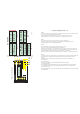
The LED meanings and functions (fig 8)
BOOST / CONSTANT CURRENT:
TIMER ON
FLOAT:
BATTERY INPUT OVER VOLTS
BATTERY OUTPUT VOLTAGE HIGH
HEAT-SINK OVER TEMP
Green: This should be on from start-up (a slow flash shows that the unit is
on but on soft-start). When this LED is on continuously this shows that the alternator should be working at it’s
maximum. It should remain on until the green float comes on and this shows the high charge rate is complete.
: Yellow: Timer Activated: This comes on, when the voltage reaches about 13.9 - 14 volts ( x 2 for 24
v ) and depending on how long it took to come, will dictate how long the timing cycle will remain on. The
software will calculate the timing for the high charge rate. This will vary from 1 - 6 hours and the time will be
displayed on the remote panel and a count down . This light will remain on until the high charge rate is over, and
will go out at the same time as the high charge rate between 1-6 hrs after activation.
Green Float Mode: This indicates that all the high charge cycles are now over and should remain on after
all the high charge lights are out. The system is now running at a standard charge rate only (about 14 volts)
regulated on the battery.
: This will warn you and switch off the boost
section, this means that your alternators own regulator has failed and the alternator will now boil and
destroy your batteries, there is simply nothing we can do about this except warn you:
This will warn you and switch off
the boost section, this means that either this unit has failed and was in the process of
overcharging your battery bank, or you have some other charging source on your output battery
bank which is overcharging the batteries and our unit thinks it is at fault ie if there was a battery
charger or solor cell which was putting out a voltage in excess of 1.5 volt above the boost voltage
of each of the different battery types. this is a fatal trip and the unit will not come back on again untill reset,
high internal voltage, fatal flaw , unit defective and must be returned
high voltage starter battery, warning only no action by our unit
high voltage drop from unit output to the end of the remote sensing cable, this is due to either to
small a cable , to long a run, deflective crimping , or cable broken. not fatal , find fault and fix , max voltage
drop between unit output and cable end is 0.8 volts this is a warning but no action from our unit
high voltage drop on the output cable ( as above ) unit shut down pending the owner to increase the
thickness of the power cables to accommodate the current being used ( see the sterling cable/current table )
short circuit on output, the parameters are , voltage below 6 volts and current in excess of 100 amps (
the software will take this as a short circuit )
. red: ( ) This device monitors both heat sinks and in the event of that
exceeding 75 deg C the unit will switch off until the temperature has been reduced. It is important not to fit the unit
inside a hot engine room or somewhere with no air flow round the unit total unit shutdown, auto reset on unit temp
droping below 65 deg c
( ) and the current lights flashing, this means the boost has been switched off ( to reduce
the heat being produced on the heat sink, if the temp keeps increasing then the l.e.d. will come on solid and trip the
unit completely
( L.E.D.on solid )
please take this warning very seriously and stop your engine as soon as possible, remove the
alternator input cable then continue your journey and have the alternator inspected and repaired
at next available place.
( L.E.D. on flashing)
L.E.D. on solid
L.E.D. Flashing constant
led 2 flash,
led 3 flash,
led 4 flash,
led 5 flash
led 6 flash
group
14141414
15151515
161616161616161616161616161616161616161616
171717171717171717171717171717171717171717
18181818
(20°C). Die Ausgleichsladungszeit beträgt mindestens 12 Std. und wird automatisch berechnet.
3) Gel USA spec: Aus irgendwelchen für uns unbekannten Gründen möchten die Amerikaner ihre eigene
Ladecharacteristic haben. Trotz der Eigenständigkeit Europas gegenüber, soll die Ladespannung
maximal 14.1V betragen. Die Ausgleichsladungszeit beträgt zwischen4-10Std. und wird automatisch
berechnet.
4) geschlossene Säurebatterien & AGM: Hier ist die maximale Ladespannung 14.4V (20°C). Die
Ausgleichsladungszeit wird automatisch berechnet und beträgt zwischen 4 und 8 Std. Einige AGM
Batterien brauchen nur 14.1 Volt, sollte dieses bei Ihnen der Fall sein, so ändern Sie die Einstellung auf
Amerikanischen Standard um. Sollten Sie Zweifel haben, fragen Sie am besten den Hersteller.
Mein Rat ist: nutzen Sie am besten gleich offene Säurebatterien, welche mit Abstand auch die günstigsten
sind. Meiden Sie Gelbatterien für schnelle Ladekreisläufe, da die Nachladerate dieser sehr langsam ist.
Bringen Sie das Gerät so nah wie möglich an der Eingangsbatterie an. Beachten Sie dabei die
vorangegangenen Punkte. Sollten Sie diese in einem abgeschlossenen Maschinenraum, wie zum Beispiel in
einem kleinen Boot, dessen Maschinenraum mit Schalldämmung isoliert wurde, anbringen wollen, dann tun
Sie dieses so tief wie nur möglich. Optimal ist es natürlich diese ausserhalb des Maschinenraums in der
Nähe der Batteriebox anzubringen. Denken Sie immer daran, dass das einzige luftgekühlte Gerät Ihre
Lichtmaschine ist. Haben Sie einen vollkommen geschlossenen Raum ohne Lüftung, dann seien Sie nicht
überrascht, wenn Sie regelmässig Ihre Lichtmaschine zerstören. Sollte der Maschinenraum vollkommen
abgedichtet sein, dann packen Sie am besten einen Lüftung von aussen an die Lichtmaschine, so dass diese
die Luft rauszieht und sich selber kühlt. So beugen Sie Lichtmaschineproblemen vor.
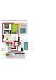
Schliessen Sie einfach den beiliegenden Temperatursensor an einen der Batteriepole an (einfach so, wie er
ist! Nicht das Kabel abklemmen oder den Sensor (im Ringterminal) beschädigen!!) und die 2 Kabelenden
werden an die entsprechende Klemme. Drücken Sie einfach den kleinen Hebel runter und stecken Sie eine
Leitung in jeder Seite ein. Es besteht keine Polung auf den Leitungen. Seien Sie sicher, dass Sie den kleinen
Temperatursensor, der sich in dem Ringterminal befindet, nicht beschädigen, da dieses den Prozessorchip
zerstören würde. Die Ausgangspannung würde sich im Vergleich zu der vom Hersteller angegebenen
Batterieladetemperaturkurve verringern, die Batterietemperatur würde 50Grad Celcius erreichen, welches
dazu führen würde, dass die Einheit die Ladung abschalten würde.
Dieses ist ein weiterer, mitgelieferter Temperatursensor, der mit dem Gehäuse der Lichtmaschine (7)
verbunden werden sollte. An dem Gerät wird dieser an der entsprechenden Klemme befestigt. Wenn die
Lichtmaschine eine Temperatur von ca. 100°C erreicht, schaltet das Gerät ab.
Die LED 15 signalisiert dieses am Gerät und an der Fernbedienung. Sobald der Generator wieder abgekühlt
ist, wird das System automatisch wieder gestartet.
Hier verbinden Sie ein Kabel von der entsprechenden Klemme mit dem Pluspol der zu ladenden Batterie.
Die Spannung wird anschliessend mit an der Batterie gemessen, um einen eventüll vorhandenen
Batterietemperatur:
Lichtmaschinen-Temperatur-überwachung:
Batterie-Spannungssensor (8):