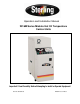
Operation and Installation Manual 2016M Series Midsize Hot Oil Temperature Control Units Important! Read Carefully Before Attempting to Install or Operate Equipment Part No. 882.88107.00 Bulletin No. SC1-640.
Write down your unit serial number(s) ________________ ________________ here for future reference ________________ ________________ ________________ ________________ ________________ ________________ ACS is committed to a continuing program of product improvement. Specifications, appearance, and dimensions described in this manual are subject to change without notice. © Copyright ACS, Inc. 2008 All rights reserved. Part No. 682.88107.00 Page 2 Revision 4 Effective 2/1/2005 Bulletin No. SC1-640.
Safety Considerations Portable hot oil temperature control units are designed to provide safe and reliable operation when installed and operated within design specifications, following national and local safety codes. To avoid possible personnel injury or equipment damage when installing, operating, or maintaining this equipment, use good judgment and follow these safe practices: ; Follow all SAFETY CODES. ; Wear SAFETY GLASSES and WORK GLOVES.
Table of Contents CHAPTER 1: GENERAL INFORMATION................................... 6 1-1 1-2 1-3 1-4 1-5 1-6 Introduction.................................................................................................................. 6 Necessary Documents ................................................................................................ 6 Models Covered .......................................................................................................... 6 Standard Features............
Charts and Figures 1 2 3 4 5 6 7 8 Portable Hot Oil Temperature Control Unit and Specifications 15 Hot Oil Temperature Control Unit Piping Setup 22 Typical E5CK Microprocessor Controller 33 Control Panel Switches 35 System Status Board Indicators 37 18-24 GPM Pump Construction 075-00370-02 45 Thrust Bearing Assembly 46 Customer-Recommended Spare Parts Portable Hot Oil Temperature Control Units 54-57 Page 5
Chapter 1: General Information 1-1 Introduction Your portable hot oil temperature control unit circulates thermal transfer-type oil through your process and to precisely, automatically, and reliably maintain it at a temperature you can select. The operating range of your temperature control unit is from 100°F to 550°F (38°C to 288°C). The unit is best suited for use with TrueTherm™ Heat Transfer Fluid.
1-4 1-5 Standard Features • Off-the-shelf microprocessor-based PID temperature controller with Process and Set Point LED readouts • Non-fused lockable rotary disconnect • Dual stage immersion heater with IEC contactors • 550°F (288ºC) maximum operating temperature {400ºF (244ºC) maximum operating temperature for 6 kW heater} • Manual bypass • Branch fusing • System status graphic display • Pressure switch for low pump pressure shut-down • NEMA 12 electrical enclosure • UL listed subpane
1-6 • Heat exchanger options of 3.9 sq. ft. (0.3627 sq. m) and 6.7 sq. ft. (0.6231 sq. m) • Remote controller • Lexan cover • Optional operating voltages of 208/3/60, 230/3/60, 575/3/60, 380/3/50, and 415/3/50 Feature Descriptions Immersion Heaters The fluid is heated by the specially designed three-phase low watt density electrical immersion heater, and regulated by the controller. The standard heater has a steel sheath for low watt density and good heat transfer.
Ful-Flo Valve A regulating by-pass line featuring a Ful-Flo valve is standard in all units. This is a safety device to prevent excessive pressure in the event that the delivery line is obstructed. Each Ful-Flo is factory preset to limit system pressure as specified by the customer. It must not be tampered with in any way. In the event of an obstruction in the line, the Ful-Flo will open and divert fluid from the delivery TO PROCESS line to the return From Process line.
Electrical System Controls The electrical controls of your temperature control unit are specially engineered for reliability, safety and simplicity of operation. The switches are clearly labeled as to their function. Your temperature control unit has a system status board so you can evaluate the status and performance of the unit at a glance. Pilot lights are provided to indicate key unit functions. An audible alarm is standard with your unit.
Pressure Switch A pressure switch is built into each unit to guard against heater damage. This feature prevents the heater elements from being energized unless the pump is running and fluid is in the system. After a preset time, the pump shuts down if the fluid pressure is not re-established. The pressure switch is preset at the factory; do not tamper with it. Safety Thermostat The safety thermostat is a J-Thermocouple sensing, adjustable, fail-safe device located in the heater tank.
Figure 1 Portable Hot Oil Temperature Control Unit Portable Hot Oil Temperature Control Unit Specifications Model Pump Dimensions Shipping Number Available heaters Power Pressure Flow H W D Weight 460 / 230 6 kW 12 kW 18 kW 24 kW hp kW PSI Bar gpm lpm in. cm in. cm in. cm lbs. Kg 9 9 10 ♠ Std. 1.0 0.75 30 2.07 18 68.1 46” 117 18¼” 46 42” 107 600 273 9 9 15 ♠ Std. 1.5 1.12 50 3.45 18 68.1 46” 117 18¼” 46 42” 107 600 273 9 9 20 ♠ Std. 2 1.49 30 2.07 24 90.8 46” 117 18¼” 46 42” 107 600 273 9 9 20 ♠ Std. 2 1.
Chapter 2: Shipping Information 2-1 Unpacking and Inspection You should inspect your portable hot oil temperature control unit for possible shipping damage. If the container and packing materials are in re-usable condition, save them for reshipment if necessary. Thoroughly check the equipment for any damage that might have occurred in transit, such as broken or loose wiring and components, loose hardware and mounting screws, etc.
2-3 If the Shipment is Not Complete Check the packing list. The apparent shortage may be intentional. Back-ordered items are noted on the packing list. You should have: ; Portable hot oil temperature control unit ; Bill of lading ; Packing list ; Operating and Installation packet ; Electrical schematic and panel layout drawings ; Component instruction manuals Re-inspect the container and packing material to see if you missed any smaller items during unpacking.
Chapter 3: Installation 3-1 Work Rules The installation, operation, and maintenance of this equipment must be conducted in accordance with all applicable work and safety codes for the installation location. This may include, but is not limited to OSHA, NEC, CSA, and any other local, national, and international regulations. 3-2 • Read and follow these instructions when installing, operating, and maintaining this equipment.
Make sure that the unit location is not in a confined space to ensure proper air circulation. Special air circulation/ventilation is required for units operating at temperatures exceeding 500ºF (260ºC). Vapors can escape from areas such as the reservoir tank during high temperature operation. ! CAUTION Harmful vapors may be generated from thermal fluid during high temperature operation. Prolonged or repeated exposure of these hot-generated vapors may result in eye and respiratory tract irritation.
The following table lists hot oil TCU pipe sizes. Size diameter Connection inches NPT mm (approx.) c To Process 1” NPT 25.4 mm From Process 1” NPT 25.4 mm Cooling Water Supply ¾” NPT 19.1 mm Cooling Water Drain ¾” NPT 19.1 mm Oil Drain ½” NPT 12.7 mm Fill Port 1” NPT 25.4 mm c Customer is responsible for converting to metric. Notes: Always use a backup wrench to support the unit piping when making connections. Make sure all external piping is supported independently of the unit.
Connecting Process Piping ! CAUTION • Hoses, valves and other components in your process must be able to withstand temperature control unit maximum temperatures and pressures. • Maximum temperatures and pressures are listed on the unit nameplate. • Carefully inspect all components before installation. • If in doubt about component suitability, obtain factory components. • Fix all leaks! Fluid can be a potential fire and slip hazard.
! CAUTION The reservoir tank must be vented to prevent pressurization. A pressurized reservoir could rupture, allowing hot fluid to escape and become a potential fire and slip hazard. Note: Heat transfer fluids expand when heated. Expansion rates vary, depending on fluid types and temperatures. For more information on expansion rates, refer to specification information for the heat transfer fluid you select. Generally, most heat transfer fluids expand at the rate of 2.
Connect the TO PROCESS hookup to the entrance of the process and the FROM PROCESS hookup to the exit of the process. Connect the COOLING WATER SUPPLY to your plant water supply. Connect the COOLING WATER DRAIN line to an open drain, or to the return line of your central water system. If returning to a central water system, use a condensate/return tank to avoid a standing water column on the heat exchanger drain line.
• Locate disconnects in an easily accessible location. Operators should not have to squeeze around the unit to reach disconnects, especially in case of emergency. • When running conduit whips to the unit, make sure that whips are routed away from hot piping.
- Notes - Page 22 Portable Hot Oil Temperature Control Units
Chapter 4: Startup Preparations 4-1 Starting the Unit Unit Start-up (With Autovent Solenoid) The highly engineered controls and controller make this unit almost self operating. Before you can begin heating, it will be necessary to perform the following start up procedures. This will ensure that all air is vented from the system to prevent fluid degradation and damage to the heater. 1. Add fluid to the reservoir tank until the level is near the top of the sight glass. 2.
Unit Start-up (With Manual Vent Valve) The highly engineered controls and controller make this unit almost self operating. Before you can begin heating, it will be necessary to perform the following start up procedures. This will ensure that all air is vented from the system to prevent fluid degradation and damage to the heater. 1. Add fluid to the reservoir tank until the level is near the top of the sight glass. 2. Open the Vent Valve on the back of the unit. 3.
The portable hot oil temperature control unit is now ready for use. All that is required is to select a process set point on the controller as described in the controller manual. Note: 4-2 If all traces of water are not removed from the system, severe cavitation may occur at elevated temperatures. Indications are a “gravely” sounding pump, fluctuating or dropping pressure, or rapidly rising fluid level in the expansion tank. Repeat Step #7 if this occurs.
If it appears that the tank may overfill, connect a line from the FILL port of the reservoir tank to a clean auxiliary container. Returning Fluid To Tank (With Manual Vent Valve) If the unit is to be moved from one process to another (i.e. mold changes, etc.), the following steps must be taken to drain the mold and process lines. Note that this is just the opposite of unit start up/air purge: 1. Cool fluid to 100 degrees °F maximum. 2. Open the Vent Valve to allow in fresh air into the pipes. 3.
- Notes - Portable Hot Oil Temperature Control Units Page 27
Chapter 5: Using Controls & Indicators 5-1 The Microprocessor Controller The controller is an easy-to-operate microprocessor-based PID control device. When the process reaches the set point, the PID control cycles the cooling valve and/or immersion heater to maintain the proper leaving water temperature. The controller has been fully factory tested. Set the desired process temperature set point and the control does the rest. Built-in range of operation on the controller is 0°F to 550°F (-18ºC to 288ºC).
STOP LED The orange STOP LED is not used. RMT LED The orange RMT LED is lit during remote operation. AT LED The orange AT LED flashes during auto-tuning. SUB1 LED The orange SUB1 LED is lit during high temperature conditions. 5-3 Using Controller Keys AT AT Key Press and hold the AT AT key for two seconds to initiate or to stop the auto-tune function. Display Key Display key change, based on how long you press it.
5-4 Identifying Control Panel Switches This section lists the descriptions and functions of the control panel switches. These switches control the operation of the unit. Figure 4 Control Panel Switches START STOP REVERSE AUTO VENT OFF MAN. COOL SILENCE Alarm Silence Mode Select Vent Cycle Start Pump Reverse Pump Stop Pump Start Pump Start Press the START button to start the pump in the normal forward direction. Pump Stop Press the STOP button to stop the pump and de-energize the controller.
to the Center Default position when in AUTO mode. The switch stays in the Maintained position in Manual Cooling mode. ! CAUTION Always let the pump run for at least one (1) minute before switching to AUTO mode. Never switch to AUTO mode when filling or venting the unit, except as described in the Unit Startup chapter. Improper switching can seriously damage the heater, as it could become energized with air in the system.
Figure 5 System Status Board Indicators PUMP OVERLOAD SYSTEM STATUS MODE PUMP REVERSE POWER ON AUTO PUMP FORWARD BYPASS RELIEF VALVE TO PROCESS LOW PRESSURE HEATER ON SAFETY THERMO STRAINER HEAT EXCHANGER FROM PROCESS HIGH LEVEL VENT WATER COOL SOLENOID FILL LOW LEVEL VENT SOLENOID DRAIN WATER SUPPLY RES. TANK Use the status board to optimize unit performance.
Vent Solenoid Indicator Light The Vent Solenoid indicator illuminates when the venting solenoid energizes during venting sequences. Mode Indicator Lights Select the unit operating mode by using the selection switch. Power On Mode Indicator Light The Power On mode indicator light illuminates to indicate that the control circuit is energized in the unit.
Low Level Indicator Light The Low Level indicator light illuminates when the heat transfer fluid level in the system is too low. This is an alarm condition, so the audible alarm activates to notify you of the low fluid level fault, and the controller outputs are disabled.
Chapter 6: Preventive Maintenance ! WARNING Make sure that your maintenance technicians comply with lock-out/tag-out procedures during any servicing or maintenance of this unit and related equipment, per OSHA article ART 1910.147. Before you begin servicing this unit, disconnect all power to the unit, let the unit cool down completely, and turn off the water.
Making Six-Month Checks • Inspect electrical connections for secure, tight electrical terminations and ground connections. Inspect the power cable, especially at the entrance point to the electrical enclosure. Have a qualified electrician perform this inspection. 6-2 • Check the mounting bolts on the pump, the motor, and the heater flange for tightness. • Remove the heat exchanger tube bundle and check it for lime and mineral deposits. Carefully clean the bundle as needed.
6-4 Corrective Maintenance Pumps and Seals Each unit is completely tested and calibrated before leaving the factory. The unit is then cooled, drained, and packed for shipment. If the unit stands idle for a long time before being installed in your factory, gaskets can dry out and possibly leak when you start the unit. In most cases, these gaskets soon swell and form a tight seal. If not, you may need to tighten the bolts to stop the leak.
Figure 6 18-24 GPM Pump Construction 075-00370-02 Page 38 Portable Hot Oil Temperature Control Units
Disassembling the Pump 1. Mark head and casing before disassembly to insure proper reassembly. The idler pin, which is offset in pump head, must be positioned toward and equal distance between port connections to allow for proper flow of liquid through pump. Remove head from pump. Do not allow idler to fall from idler pin. Tilt top of head back when removing to prevent this. Avoid damaging head gasket. 2. Remove idler and bushing assembly. 3.
11. Clean all parts thoroughly and examine for wear and damage. Check lip seals, ball bearing, bushings and idler pin and replace if necessary. Check all other parts for nicks, burrs, excessive wear and replace if necessary. Wash bearings in clean solvent. Blow out bearings with compressed air. Do not allow bearings to spin; turn them slowly by hand. Spinning bearings will damage race and balls. Make sure bearings are clean, then lubricate with non-detergent SAE 30 weight oil and check for roughness.
3. Coat idler pin with non-detergent SAE 30 weight oil and place idler and bushing on idler pin in head. If replacing with carbon graphite bushing, Refer to Installation of Carbon Graphite Bushings, page 50. 4. Using a .010 to .015 inch head gasket, install head and idler assembly on pump. Pump head and casing were marked before disassembly to insure proper reassembly.
Thrust Bearing Adjustment 1. Loosen axial setscrews in face of end cap on the thrust bearing assembly. If rotor shaft cannot be turned by hand, back off the thrust bearing assembly until there is a noticeable drag of the shaft. Note mechanical seal will provide some drag and this is a normal condition. The thrust bearing assembly must be turned in until it can just be turned over by hand. This ensures the rotor is against the head and a zero end clearance condition exists. 2.
Installation of Carbon Graphite Bushings When installing carbon graphite bushings, extreme care must be taken to prevent breaking. Carbon graphite is a brittle material and easily cracked. If cracked, the bushing will quickly disintegrate. Using a lubricant and adding a chamfer on the bushing and the mating part will help in installation. The additional precautions listed below must be followed for proper installation: 1. A press must be used for installation. 2. Be certain bushing is started straight. 3.
Note: Make sure the idler doesn’t slide off the idler pin during head removal to avoid damage and personal injury. Cleaning the Pump A clean pump is easier to inspect, lubricate, and adjust; it runs better and looks better! Storing Your Portable Hot Oil Temperature Control Unit If you anticipate that your unit will be out of service or stored for a long time, flush and drain the pump and circulating system to protect it from freeze-ups or rusting. See Section 6-3 on Page 35 for more information.
Portable Hot Oil Temperature Control Units Page 45
Figure 8 Customer Recommended Spare Parts Immersion Heaters Part number 722-00138-07 722-00138-08 722-00138-09 722-00138-10 722-00138-11 722-00138-12 Description HTR, IMM, 12 KW, 208 V, 3”, 6 ELE HTR, IMM, 12 KW, 240 V, 3”, 6 ELE HTR, IMM, 12 KW, 380 V, 3”, 6 ELE HTR, IMM, 12 KW, 415 V, 3”, 6 ELE HTR, IMM, 12 KW, 480 V, 3”, 6 ELE HTR, IMM, 12 KW, 600 V, 3”, 6 ELE Note: 6 kW heaters are modified 12 kW heaters; jumpers are remove from one leg.
Figure 8 Customer Recommended Spare Parts Cont’d. Pressure Gauge Part number 037-00119-00 Description GAUGE, PRESSURE, 0 — 100 PSI Optional Heat Exchangers; Tube Bundle Only Ass’y. part no. 106-00267-00 106-00268-00 Tube bundle only part no. 162-00047-10 162-00047-11 Description 3.9 SQ. FT. TCO 550°F 6.7 SQ. FT.
Figure 8 Customer Recommended Spare Parts Cont’d.
Figure 8 Customer Recommended Spare Parts Cont’d.
7 Troubleshooting Condition Possible cause Undersized connectors/lines. Long connecting lines between unit and mold. Serpentine flow through mold. Blocked line in mold. Temperature fluctuations/rapid cycling from hot to cold. Quick disconnect fitting with check valve. Carbon build-up in unit piping or fittings. Faulty TCU. Reversed probes. Loss of fluid in process. Vent valve open. Unit does not heat properly/can not achieve set point.
Troubleshooting Cont’d. Condition Unit does not heat. (cont’d.) Unit overheats/unable to cool. Possible cause Controller heater output open. Clogged Y strainer. Water supply to unit is turned OFF. Water drain is plugged or excessive back pressure in drain line. Heat exchanger tubes plugged by lime deposits. Faulty solenoid valve. Leaks in connecting lines. Air in circulating lines. Low fluid. Defective Ful-Flo valve. Rapid drop in pressure/no pressure. Water in fluid. Vent solenoid open.
DIAGRAMS FLOW & ELEMENTARY ELECTRICAL Please refer to Electrical Drawings Provided in Packet with Unit Page 52 Portable Hot Oil Temperature Control Units
Service Notes Portable Hot Oil Temperature Control Units Page 53
Service Notes Page 54 Portable Hot Oil Temperature Control Units
Service Notes Portable Hot Oil Temperature Control Units Page 55
Service Notes Page 56 Portable Hot Oil Temperature Control Units
Service Notes Portable Hot Oil Temperature Control Units Page 57
Index Adjusting bin level monitor sensitivity, Error! Not a valid bookmark in entry on page 40 Adjusting End Clearance, 51 Air Purge, 13 Alarm Silence, 36 Alarm Silence, 12, 12 AT key, 34 AT LED, 34 Available Options, 9 Charts and Figures, 6 Connecting Cooling Water Piping, 21 Connecting Piping, 19 Connecting Process Piping, 21 Connecting Vent Piping, 21 Connection Lines, 11 Control Unit Specifications, 15 Controller display, 33 Cool Solenoid Indicator Light, 38 Corrective Maintenance, 42 Pumps and Seals, 4
Technical Assistance Parts Department Call toll-free 7am–5pm CST [800] 423-3183 or call [262] 641-8610, Fax [262] 641-8653 The ACS Customer Service Group will provide your company with genuine OEM quality parts manufactured to engineering design specifications, which will maximize your equipment’s performance and efficiency. To assist in expediting your phone or fax order, please have the model and serial number of your unit when you contact us.