Operation and Installation Manual GP Series Portable Chillers Part Number: 882.12047.
Write Down Your Serial Numbers Here For Future Reference: _________________________ _________________________ _________________________ _________________________ _________________________ _________________________ We are committed to a continuing program of product improvement. Specifications, appearance, and dimensions described in this manual are subject to change without notice. ECN No. ____________ © Copyright 2013 All rights reserved.
Shipping Information Unpacking and Inspection You should inspect your equipment for possible shipping damage. Thoroughly check the equipment for any damage that might have occurred in transit, such as broken or loose wiring and components, loose hardware and mounting screws, etc. In the Event of Shipping Damage According to the contract terms and conditions of the Carrier, the responsibility of the Shipper ends at the time and place of shipment.
Returns Do not return any damaged or incorrect items until you receive shipping instructions from the shipping department. Credit Returns Prior to the return of any material, authorization must be given by the manufacturer. A RMA number will be assigned for the equipment to be returned. Reason for requesting the return must be given. ALL returned material purchased from the manufacturer returned is subject to 15% ($75.00 minimum) restocking charge. ALL returns are to be shipped prepaid.
Table of Contents CHAPTER 1: SAFETY ................................................................ 7 1-1 How to Use This Manual ............................................................................................... 7 Safety Symbols Used in this Manual ..................................................................... 7 1-2 Warnings and Precautions ............................................................................................ 9 1-3 Responsibility ..
4-4 4-5 4-6 4-7 4-8 Access Levels ............................................................................................................. 45 Controller Setpoints ..................................................................................................... 45 Configuration Settings ................................................................................................. 49 Alarms ...........................................................................
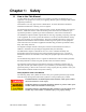
Chapter 1: 1-1 Safety How to Use This Manual Use this manual as a guide and reference for installing, operating, and maintaining your equipment. The purpose is to assist you in applying efficient, proven techniques that enhance equipment productivity. This manual covers only light corrective maintenance. No other maintenance should be undertaken without first contacting a service engineer. The Functional Description section outlines models covered, standard features, and optional features.
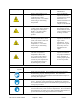
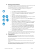
Hazard Alert Symbol Mandatory Symbol Description/Explanation Preventative Maintenance High Voltage Hazard. The electrical enclosure is supplied with 3-phase electrical power. Use caution when using or maintaining this product. Every six months inspect all electrical connections for secure attachment. For further information see the Maintenance Chapter in this manual Cut/Crush Hazard. The air cooled version of this product has high speed rotating fan blades.
1-2 Warnings and Precautions Our equipment is designed to provide safe and reliable operation when installed and operated within design specifications, following national and local safety codes. To avoid possible personal injury or equipment damage when installing, operating, or maintaining this equipment, use good judgment and follow these safe practices: ü Follow all SAFETY CODES. ü Wear SAFETY GLASSES and WORK GLOVES. ü Disconnect and/or lock out power before servicing or maintaining the equipment.
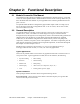
Chapter 2: 2-1 Functional Description Models Covered in This Manual This manual provides operation, installation, and maintenance instructions for air-, water-and remote air-cooled portable chillers. Model numbers are listed on the serial tag. Make sure you know the model and serial number of your equipment before contacting the manufacturer for parts or service.
Process Fluid Temperature – The standard range for the leaving fluid temperature for this series of packaged chillers is 20°F to 80°F (-6.7°C to 26.7°C). When the process requires fluid temperatures below 45°F (27.2°C) it is imperative that the process fluid is a mix of an industrial grade ethylene or propylene glycol and water to the proper percentage (by volume) to protect the system. See Chapter 3 for a further discussion regarding the use of glycol within the system for these applications.
Refrigeration Circuit Air-, water-, and remote air-cooled refrigerant condensing differ only in the way the compressed gas is condensed to a liquid. Shown below is a water-cooled version. The refrigerant is compressed in the compressor and flows through the discharge line as a gas to the condenser. There it gives up its heat as it condenses to a liquid in the condenser.
differential” value the controller will enable the compressor; if equipped with two compressors the controller will enable the one with the least amount of hours. The second compressor will be enabled if the leaving fluid temperature remains above the setpoint plus the “compressor on differential” value for more than 60 seconds. The hot gas valve is designed to trim the load of one compressor and will modulate in order to meet the desired leaving fluid setpoint via a PID algorithm.
Air-Cooled Condenser – Aluminum fin/ tube with washable filters, packaged units only. Variable speed fan control standard for all remote air cooled condensers and GPAC70 through 210. Optional on GPAC20 through 50. Water-Cooled Condenser – Tube-in-tube condensers (GPWC20 – GPWC50), Shell-andtube condensers (GPWC70 – GPWC210). All come with electronic cooling water regulating valves. Remote Air-Cooled Condenser– Aluminum fin/tube with low ambient control down to –20ºF (-29ºC) via variable-speed fan(s).
• Multiple refrigeration access ports • Liquid line shut-off ball valves • Filter-dryer • Sight glass • Externally equalized thermal expansion valve • Liquid line solenoid • Compressor crankcase heater Controller Features • Off-the-shelf microprocessor-based PID controller with To Process, From Process and Set Point readout • Time delay for proof of water flow/pressure (models w/pump only) • Low refrigerant pressure time delay for low ambient start-up on remote air-cooled and air-cooled chillers with the va
High Pressure Cutout This electro-mechanical cutout device opens the compressor control circuit if the refrigeration system compressor discharge pressure exceeds 575 psig. The high-pressure cutout is a manual reset device typically mounted on the compressor discharge line inside the mechanical cabinet. Call a refrigeration service technician to analyze the problem and reset the control.
Flow Switch The thermal dispersion flow switch cutout device, mounted in the process piping, shuts down the chiller if it senses that the water/glycol flow rate through the evaporator has dropped below an acceptable level. The flow switch opens the control circuit and shuts down the pump and the chiller. Remote Start/Stop Interlock An additional contact is provided to allow the remote starting or stopping of the chiller.
Stainless Steel Reservoir. Manufactured from 304 stainless steel. Mounting Features. Mounting rails with feet – GP20-GP105 indoor units. Standard on GP140-GP210 and all outdoor packaged units. Optional Operating Voltages. 208-230/3/60, 460/3/60, 575/3/60, and 400/3/50 volt available UL/cUL Labeled Electrical Subpanel. This option provides for the subpanel to be listed with Underwriters Laboratory, with UL-related benefits and features. Sub-panels marked by the UL/cUL sticker are accepted within Canada.
Chapter 3: 3-1 Installation Uncrating All models are shipped mounted on a skid, enclosed in a plastic wrapper, and open-crated on all four sides and top. 1. Pry the crating away from the skid. 2. Use a pry bar to remove the blocks securing the unit to the skid. 3. Lift unit from sides, inserting forklift under the base. The forks must be equidistant from the centerline of the unit and the unit must be balanced on the forks. Lift slowly and only high enough to clear the skid.
3-3 Process Water Connections All of our portable chillers have two chilled water connections. The chilled water supply, labeled “To Process” is the outlet for the chilled water leading to the process being cooled. The chilled water return, labeled “From Process” is the inlet leading from the process back into the chiller to be cooled and re-circulated. Figure 2: Typical GP20-50 Air Cooled Process Piping Connections All external chilled water connections should be run full size to the process.
3-5 Galvanic Corrosion Considerations The materials used in the water circuit piping of these chillers are non-ferrous and react electro-chemically with ferrous metallic materials. Some water has dissolved minerals that greatly accelerate the reaction between dissimilar metals. PVC or non-ferrous piping is recommended to reduce galvanic action. If iron piping must be used, use dielectric unions at the chiller, and water treatment is required.
Figure 3: Typical GP20-50 Water Cooled Condenser Connections Air-Cooled Chiller Condensers Air-cooled chillers use the surrounding air to cool the condenser. Install the chiller in an area where there is free passage of air for condensing and provisions for removal of heated air from the area. Do not locate air-cooled chillers in locations where steam, hot air, or fume exhausts can be drawn into the chiller. ! Clean air-cooled condensers and filters frequently.
Remote Air-Cooled Chiller Condensers Remote air-cooled portable chillers are shipped with nitrogen holding charge and a full charge of oil (excluding the amount needed for field piping). The remote air condenser is shipped with a dry nitrogen charge. Verify that the holding charge has not been lost prior to installation. If there is no pressure, leak test the unit and repair before installing the interconnecting refrigerant piping. Read this entire section before installation.
• Refrigeration lines must not be crossed, i.e., chiller liquid lines are to be piped to condenser liquid lines. Sizing Refrigerant Lines. To determine field installed liquid and discharge line sizes, first establish the equivalent length of pipe for each line, valve, and elbow. Chiller capacity and leaving water temperature range is also required. See Figure 4 on page 24 for lengths of refrigerant valves and fittings. Liquid Line Sizing.
GPRC-40 GPRC-50 Liquid Line Size (OD") Total Equiv. Length (Ft) 25 50 75 100 125 150 175 200 225 250 275 300 Liquid Line Size (OD") Horizontal or Downflow Upflow 1-5 Ft Upflow 6-10 Ft Upflow 11-15 Ft 5/8 5/8 5/8 5/8 3/4 3/4 3/4 3/4 3/4 3/4 3/4 3/4 5/8 5/8 5/8 3/4 3/4 3/4 3/4 3/4 3/4 3/4 3/4 3/4 5/8 3/4 3/4 3/4 3/4 3/4 3/4 3/4 7/8 7/8 7/8 7/8 3/4 3/4 3/4 3/4 7/8 7/8 7/8 7/8 7/8 7/8 7/8 7/8 GPRC-70 Total Equiv.
GPRC-105 GPRC-140 Liquid Line Size (OD") Liquid Line Size (OD") Total Equiv. Length (Ft) Horizontal or Downflow Upflow 1-5 Ft Upflow 6-10 Ft Upflow 11-15 Ft Total Equiv.
Figure 6: Discharge Line Sizing Horizontal or Downflow Discharge Line Sizes (OD") Total Equivalent Length (Ft) Model 25 50 75 100 125 150 175 200 225 250 275 300 GPRC-20 5/8 5/8 5/8 5/8 3/4 3/4 3/4 3/4 3/4 3/4 3/4 7/8 GPRC-30 7/8 7/8 7/8 7/8 7/8 7/8 7/8 7/8 7/8 7/8 7/8 7/8 GPRC-40 7/8 7/8 7/8 7/8 7/8 7/8 7/8 1-1/8 1-1/8 1-1/8 1-1/8 1-1/8 GPRC-50 7/8 7/8 1-1/8 1-1/8 1-1/8 1-1/8 1-1/8 1-1/8 1-1/8 1-1/8 1-3/8 1-3/8 GPRC-70 7/8 1-1/8 1-1/8 1-3
Refrigerant Charge Determination. The approximate amount of refrigerant charge required by the system varies based on the total length of the refrigerant lines and the size of the chiller. Referring to Figure 7, determine the amount of charge based on the model of the chiller and the amount of charge based on discharge and liquid line sizes and lengths. Add these three numbers together to find the final operating charge.
GP Series Portable Chillers Chapter 3: Installation 29 of 93
Figure 8: Remote Condenser Configurations Figure 9: Double Riser Detail 3-8 Checking Motor Direction All of our portable chillers have their motor rotations properly phased at the factory. If compressors, pumps, or fans are running in reverse rotation, disconnect and lock out the power source and reverse any two power leads into the chiller disconnect switch. Do not switch leads at the motors, motor starters, or contactors.
3-9 Water Reservoir The standard water reservoir is rotationally molded polyethylene with a removable lid. The tank is fully insulated to assist maintaining fluid temperature. All portable chillers shipped during the fall, winter, or spring, or those units that are shipped from stock are flushed at the factory with a water/ethylene glycol solution to prevent piping components prone to retaining water from freezing.
Figure 10: Suggested Overhead Piping Configuration GP Series Portable Chillers Chapter 3: Installation 32 of 93
Figure 11: Ethylene Glycol and Propylene Glycol Curves Percent Glycol Curves for Freeze Protection 40.0 30.0 Ethylene Glycol 20.0 Propylene Glycol 10.0 0.0 -10.0 -20.0 -30.0 -40.0 -50.0 -60.0 0.0 10.0 20.0 30.0 40.0 50.0 60.0 % Glycol by Volume Example: 45°F set point minus 20°F = 25°F. From Figure 28, 25°F equates to 10% by volume of glycol required. The standard pumps used in the GPAC Serice chillers are not recommended to be used with fluid below 0°F (-18°C).
3-10 Automatic Water Make-Up Option The chiller may be connected to an automatic make-up system if the optional package (pipe fittings, solenoid valve and 1/2” NPT city water make-up connection) is factory installed. When the unit is selected with the optional, closed stainless steel tank, a pressure reducing valve is added to the automatic water make-up option. This valve is set to be full open at 5 psig (0.3 bar).
To Process From Process • Complete chilled water To Process and From Process connections. It is suggested that shut-off valves are added to unit to control the flow rate to process and for completely isolating the chiller from the process. • If the optional automatic water makeup system was not installed on the chiller, remove the side panel to the left of the process connections and fill the tank and chilled water circuit piping until the tank is approximately ¾ full.
Operating the chiller setpoint below 45°F (7°C) without the proper amount of glycol for freeze protection could result in a damaged evaporator. ACS Group does not warrant the freeze up of the evaporator under any circumstances. • The air-cooled condenser should have an adequate supply of 75º to 115ºF (24º to 46ºC) air for proper operation.
3-12 Finishing Setup: Setting Up Passwords You can establish passwords for two levels of security: operators and supervisors. The controller comes from the factory with neither password set. This allows every user access to all functions. If you choose to establish passwords store them in a secure location because if they are forgotten there is no way to reset them without a service call. Operator Password.
To set password protections: 1. Press the button to access the menu screen. 2. Press the or to highlight SETPOINTS, and press 3. Press the Password or until the following screen appears for the Operator or Supervisor 4. Press to accept the screen, and then press Password line is highlighted. 5. Press or 0 and 9999. 6. Press . until the Operator or Supervisor to increment or decrement the number. The password can be between to accept the Password and move to the next line. 7.
Chapter 4: 4-1 Operation Panel Buttons, Indicator Lights, and Switches Microprocessor Controller The standard chillers use a microprocessor-based PID controller. The Carel PCO controller is located in the control enclosure. The Carel PGD1 Interface is housed in a block of rigid plastic with a magnetic backing that allows the user to “stick” the interface on any metallic surface.
Button 4-2 Button Description Detailed description Menu Button Used to access the menus structure of the PGD interface On/Off Button Used to turn the entire chiller On or Off. The button is backlit and will turn amber when the chiller is On. Back Button Used to back up from a menu and return to the main status screen Up Arrow Button Used to increment a data field or scroll up within a menu structure. Enter Button Used to accept a data field value or to select a menu item.
Enter the established Operator Password by depressing the to move the position of the cursor, and then depressing the or button to increment or decrement the number. Once all of the numbers have been entered depress the appear. to accept the password. The following screen will Figure 15: Operator Setpoints Screen 5. Depress to move the cursor to the CHILLED FLUID SP line. Use the or button to increment or decrement the value. Depress accept the value and move the cursor down one line. 6.
4-3 Status Screens The controller has eight (8) preconfigured status screens. The main status screen (shown in Figure Figure 16) shows the main operating points of the chiller: Entering and Leaving fluid temperatures; Leaving fluid setpoint, pump discharge pressure, tank fluid level (depth), and percentage of hot-gas bypass output. Figure 16: Main Chiller Status Screen Depressing cycles through the following screens (shown below) – Analog I/O, Digital I/O, and Test.
GP Series Portable Chillers Chapter 4: Operation 43 of 93
The chiller can be equipped with a tempered fluid loop inside of the chiller. If this option is installed, the main screen changes to the following.
4-4 Access Levels The controller is setup to allow access to three distinct password groups: operator, supervisor, and service. Operator access allows the user to modify the Leaving Water Temp, Hi Temp Warning, and Hi Temp Fault setpoints. Supervisor access allows the supervisor to modify the above plus Selecting any of the menus in the Menu Screen will display the Password Screen.
Variable Chil Hi Temp Dly Hi Temp Flt Type Chil Lo T Wrn Dif Chil Lo T Flt Dif Comp, Lead Cmp On Delay Comp, Lead Cmp Off Delay Lag Cmp On Dly Lag Cmp Off Dly Cond Fan Start Cond Fan Stop Pump Stop Delay Heater On Delay Heater Cycle Tm Description Access Level Operator Supervisor Time (in seconds) Chilled High Temperature alarm is ignored before activating When set to CRIT, chiller and process high temp alarms will deactivate compressors and pumps.
Variable Tank Max Lvl Low Level Fault Low Level Warning Wtr Makeup On Wtr Makeup Off High Lvl Warning High Lvl Fault Description Access Level Operator Supervisor Maximum tank level. Used to set the default high tank level alarm setpoints as well as the auto-water makeup off setpoint.
Enter the Operator Password by depressing the to move the position of the cursor, and then depressing the or button to increment or decrement the number. Once all of the numbers have been entered depress the to accept the password. The following screen will appear. Figure 18: Operator Setpoints Screen 3. Depress to move the cursor to the Leaving Temp line. Use the button to increment or decrement the value. Depress value and move the cursor down one line. to accept the 4.
4-6 Configuration Settings Within the Supervisor Menu the chiller can be configured if options are added in the field. These configurations are described below.
Variable Analog Out 3 Analog Out 4 Digital In 8 Start Mode Chil Cntl Sens Proc Cntl Sens Pump 2 OL Alm Flow 2 Alm Type Alarm Out Network Prot Network Baudrate Network Address Units GP Series Portable Chillers Description Access Level Operator Supervisor Determines how analog output 3 is used.
4-7 Alarms The controller is setup with multiple alarms, most of them configurable using the Supervisor password. Section 4-5 Controller Setpoints on page 45 gives a list of alarms that the controller is setup to display. The alarms are broken up into two categories – warnings and faults. The warning notifies the user that the parameter has been exceeded and the chiller is allowed to keep operating, but should be monitored to determine the cause of the warning.
Chapter 5: 5-1 Maintenance Lubrication Grease all fan motors, and pump motors that do not have permanently sealed bearings. Be sure to use an all-purpose industrial grease with a temperature reference of 185˚ F (85˚ C). Remove the grease relief plug (motors only) before adding grease, add grease until a small amount pours out, and replace the plug when finished. Failure to remove the grease relief plug will result in dislodging the bearing grease seal, eventually causing bearing failure.
circulating Liquid Inhibited Acid De-Scaling Solution (Part No. A0502600) through the tube water side of the condenser. Follow the directions on the container. The refrigerant side is sealed and requires no routine maintenance. Do not use steam or water over 140ºF (60ºC) to clean a condenser unless you are monitoring the refrigeration circuit for excessive pressure with gauges. Only a trained technician should use this method.
Chapter 6: Troubleshooting Many problems that can occur while operating the chiller can be avoided by following the recommended installation, operation, and maintenance outlined within this manual. If you do have a problem this Chapter will help you determine the cause and the potential solution. Before beginning the troubleshooting process • Locate all wiring, piping, and assembly drawings that were shipped with the chiller. The diagrams will note any custom options not covered in this manual.
CC = Compressor Critical Alarm Name SC = System Critical PC = Process Critical W = Warning # Type Possible Cause Solution Allow the compressor to cool MCP Failure down. If the compressor does not restart, disconnect power Compressor Fault 1 CC Compressor module has failed and verify operation of the MCP internal module. Replace if necessary. Sensor Failure Check the wiring connection at Electrical connection at Discharge Pressure Sensor Failure 2 W the sensor, and at the controller.
CC = Compressor Critical Alarm Name Low Discharge Pressure Fault Low Fluid Temp Fault Low Suction Pressure Fault Low Superheat Fault (only will appear if optional sensor pack is installed) Suction Pressure Sensor Failure Leaving Water Temp Sensor Failure Low Level Fault No Flow GP Series Portable Chillers SC = System Critical PC = Process Critical W = Warning # Type Possible Cause Solution Verify ambient air temperature Ambient air or condenser and air flow or condenser inlet water temperature too
CC = Compressor Critical Alarm Name SC = System Critical PC = Process Critical W = Warning # Type Possible Cause Solution Verify motor circuit protector Motor circuit protector open operation. Verify motor wiring and amp draw while under load. Verify system valves are Pump Overload 16 SC operational and properly set. Pump flow rate in excess of Contact customer service or capacity sales if pump is sized too small for application. Fluid temperature higher than Verify parameter and adjust if parameter.
CC = Compressor Critical Alarm Name SC = System Critical PC = Process Critical W = Warning Solution # Type Possible Cause Fluid level higher than Verify value in parameter parameter setting. Open drain valve and remove High Level Fault 24 W Too much fluid in system some fluid from system so that level is below high level fault. Replace sensor Tank sensor failure Fluid level higher than Verify value in parameter parameter setting.
CC = Compressor Critical Alarm Name Pump Flow Sensor Failure Pump Pressure Sensor Failure Refrig Liquid Temp Sensor Failure Refrig Suction Temp Sensor Failure Tank Level Sensor Failure Water make-up failure Auxilliary Alarm Low Suction Pressure at Startup SC = System Critical PC = Process Critical W = Warning # Type Possible Cause Solution Verify wiring of flow sensor at 34 W Optional flow sensor failed sensor and terminal block of controller Sensor wires loose from controller terminal block Verify wi
CC = Compressor Critical Alarm Name Pump 2 Overload High Temp Safety Switch Phase Monitor Fault From Proc Sensor Failure SC = System Critical PC = Process Critical W = Warning # Type Possible Cause Solution Verify motor circuit protector Motor circuit protector open operation. Verify motor wiring and amp draw while under load. Verify system valves are 53 SC/W operational and properly set. Pump flow rate in excess of Contact customer service or capacity sales if pump is sized too small for application.
Problem Possible cause Leaving fluid setpoint set higher than temperature of liquid in system. Compressor internal overload or MCP is open. Pump runs; compressor does not. Compressor contactor holding coil open. Defective compressor auxiliary contact. Broken wire in the compressor control circuit. Plugged Y-strainer Hot gas not coming on Pump runs, compressor cycles at short intervals. Low process water flow Restricted condenser air flow. Unit runs continuously, but not enough cooling power.
Chapter 7: 7-1 Appendix Technical Assistance Parts and Service Department The ACS Customer Service Group will provide your company with genuine OEM quality parts manufactured to engineering design specifications, which will maximize your equipment’s performance and efficiency. To assist in expediting your phone or fax order, please have the model and serial number of your unit when you contact us. A customer replacement parts list is included in this manual for your convenience.
Specifications Air-Cooled Portable Chillers Nominal operating parameters for air-cooled models are 50ºF (10ºC) leaving water temperature at 2.4 gpm per ton (9.1 lpm per 3.517 kW) with 95ºF (35ºC) ambient air. For 50 Hz applications, multiply capacity by 0.83. Nominal 60 Hz capacity flow rate must be maintained. GPAC-20 PERFORMANCE (NOMINAL DESIGN CONDITIONS) COOLING CAPACITY 4.
GPAC-40 PERFORMANCE (NOMINAL DESIGN CONDITIONS) COOLING CAPACITY 9.91 TONS ALTITUDE SEA LEVEL COOLANT SUPPLY TEMPERATURE 50 °F COMPRESSOR POWER 10070 WATTS AMBIENT AIR TEMPERATURE 95 °F EER 11.
GPAC-70 PERFORMANCE (NOMINAL DESIGN CONDITIONS) COOLING CAPACITY 20.16 TONS ALTITUDE SEA LEVEL COOLANT SUPPLY TEMPERATURE 50 °F COMPRESSOR POWER 20048 WATTS AMBIENT AIR TEMPERATURE 95 °F EER 12.
GPAC-105 PERFORMANCE (NOMINAL DESIGN CONDITIONS) COOLING CAPACITY 30.21 COOLANT SUPPLY TEMPERATURE AMBIENT AIR TEMPERATURE COOLANT TONS °F COMPRESSOR POWER 95 °F WATER COOLANT FLOW UNIT PRESSURE DROP ALTITUDE 50 SEA LEVEL 29731 WATTS EER 12.
GPAC-175 PERFORMANCE (NOMINAL DESIGN CONDITIONS) COOLING CAPACITY 49.41 TONS ALTITUDE SEA LEVEL COOLANT SUPPLY TEMPERATURE 50 °F COMPRESSOR POWER 48693 WATTS AMBIENT AIR TEMPERATURE 95 °F EER 12.
Water-Cooled Portable Chillers Nominal operating parameters for water-cooled models are 50ºF (10ºC) leaving water temperature at 2.4 gpm per ton (9.1 lpm per 3.517 kW) with 85ºF (29ºC) tower water. For 50 Hz applications, multiply capacity by 0.83. Nominal 60 Hz capacity flow rate must be maintained. GPWC-20 PERFORMANCE (NOMINAL DESIGN CONDITIONS, 60 HZ) COOLING CAPACITY COOLANT SUPPLY TEMPERATURE CONDENSER INLET WATER TEMPERATURE COOLANT 5.
GPWC-40 PERFORMANCE (NOMINAL DESIGN CONDITIONS) COOLING CAPACITY COOLANT SUPPLY TEMPERATURE CONDENSER INLET WATER TEMPERATURE COOLANT 10.94 TONS UNIT PRESSURE DROP SEA LEVEL °F COMPRESSOR POWER 8450 WATTS 85 °F EER 15.53 BTU/WATT CONDENSER WATER FLOW 33.
GPWC-70 PERFORMANCE (NOMINAL DESIGN CONDITIONS) COOLING CAPACITY 22.68 TONS ALTITUDE SEA LEVEL COOLANT SUPPLY TEMPERATURE 50 °F COMPRESSOR POWER 16970 WATTS CONDENSER INLET WATER TEMP 85 °F EER 16.
GPWC-105 PERFORMANCE (NOMINAL DESIGN CONDITIONS) COOLING CAPACITY 33.64 TONS ALTITUDE SEA LEVEL COOLANT SUPPLY TEMPERATURE 50 °F COMPRESSOR POWER 25508 WATTS CONDENSER INLET WATER TEMP 85 °F EER 15.
GPWC-175 PERFORMANCE (NOMINAL DESIGN CONDITIONS) COOLING CAPACITY 54.46 TONS ALTITUDE SEA LEVEL COOLANT SUPPLY TEMPERATURE 50 °F COMPRESSOR POWER 41633 WATTS CONDENSER INLET WATER TEMP 85 °F EER 15.
7-2 Pump Curves, Flow, and Pressure Considerations 60 Hertz Pump Curves 20-50 ALL 60 Hz ACS CHILLER PUMPS September 8, 2009 300 120 250 100 10 HP 3U 32-200-1100D3G 200 80 3 HP 2CDU 70/306 150 Psi Head [ft] 5 HP 2CDU 200/506 60 2 HP CDU 70/520D3G 3 HP CDU120/530D3G 100 40 1.5 HP CDU 70/315D3G 50 20 0 0 0 10 20 30 40 50 60 70 80 Capacity [Gal/min] HP 1.
70-210 ALL 60 Hz ACS CHILLER PUMPS September 8, 2009 300 120 250 100 15 HP 3U 40-200B150D3G 200 5 HP 2CDU 200/506 10 HP 3U 32-200-1100D3G 80 150 Bar Head [ft] 30 HP 3UB 65-200300D3G 5 HP 3U 32-160B50D3G 10 HP 3U 40-160-1100D3G 60 7.5 HP 3U 40-160-75D3G 5 HP CDU200/550D3G 100 5 HP 3U 40-125B-50D3G 50 40 20 0 0 60 120 180 240 0 300 Capacity [Gal/min] HP 5 5 5 5 7.
50 Hertz Pump Curves 20-50 ALL 50 Hz ACS CHILLER PUMPS September 8, 2009 70 6 60 10 HP 3U 32-200-1100D3G 5 50 40 4 Bar Head [m] 5 HP 2CDU 200/506 3 HP 2CDU 70/306 3 30 2 20 2 HP CDU 70/520D3G 3 HP CDU120/530D3G 1.5 HP CDU 70/315D3G 1 10 0 0 50 100 150 200 250 0 300 Capacity [liter/min] HP 1.
70-210 ALL 50 Hz ACS CHILLER PUMPS September 8, 2009 70 7 60 6 5 HP 2CDU 200/506 50 10 HP 3U 32-200-1100D3G 30 HP 3UB 65-200300D3G 5 Head [m] 5 HP 3U 32-160B50D3G 10 HP 3U 40-160-1100D3G 4 30 7.5 HP 3U 40-160-75D3G 3 5 HP 3U 40-125B-50D3G 20 5 HP CDU200/550D3G 2 10 1 0 0 120 240 360 480 600 720 840 960 1080 0 1200 Capacity [liter/min] HP 5 5 5 5 7.
Pure Water at >40°F GPXC-20 GPXC-30 GPXC-40 GPXC-50 GPM DP (PSI) GPM DP (PSI) GPM DP (PSI) GPM DP (PSI) 0.5X Nominal 6 1.0X Nominal 12 1.7 9 1.7 12 1.6 18 1.8 5.9 18 6.1 24 5.8 36 2.0X Nominal 24 6.4 21.4 36 21.9 48 20.7 72 23.3 0.5X Nominal 24 1.7 30 1.8 36 1.7 48 1.8 1.0X Nominal 48 6.1 60 6.5 72 6.1 96 6.4 2.0X Nominal 96 21.9 120 23.5 144 22.1 192 23.6 0.5X Nominal 72 1.0X Nominal 144 6.2 2.0X Nominal 288 22.
7-3 Remote Air-Cooled Chiller Configurations GP Series Portable Chillers Chapter 7: Appendix 78 of 93
Figure 19: Double Riser Detail GP Series Portable Chillers Chapter 7: Appendix 79 of 93
7-4 Typical Ductwork for Air-Cooled Chillers Fan Model GPAC-20 GPAC-30 GPAC-40 GPAC-50 GPAC-70 GPAC-90 GPAC-105 GPAC-140 GPAC-175 GPAC-210 HP 0.5 1.0 1.0 2.0 (2) 1.0 (2) 2.0 (2) 2.0 (3) 2.0 (3) 2.0 (4) 2.0 kW 0.4 0.7 0.7 1.5 (2) 0.7 (2) 1.4 (2) 1.4 (3) 1.4 (3) 1.4 (4) 1.
Notes: • Customer use of ductwork requires the high pressure fan option. • Allow 30 in. (77 cm) minimum clearance around the chiller footprint to facilitate free passage of cooling air and service accessibility. • Figure 20 shows the pressure loss per foot of ductwork. Calculate the total equivalent length before using the data below. • Support ductwork from the building structure, not off of the chiller. • Back draft damper to outside must be closed at all times when fan/blower is not operating.
7-5 Piping Diagrams GP Series Portable Chillers Chapter 7: Appendix 82 of 93
GP Series Portable Chillers Chapter 7: Appendix 83 of 93
GP Series Portable Chillers Chapter 7: Appendix 84 of 93
GP Series Portable Chillers Chapter 7: Appendix 85 of 93
GP Series Portable Chillers Chapter 7: Appendix 86 of 93
GP Series Portable Chillers Chapter 7: Appendix 87 of 93
GP Series Portable Chillers Chapter 7: Appendix 88 of 93
GP Series Portable Chillers Chapter 7: Appendix 89 of 93
GP Series Portable Chillers Chapter 7: Appendix 90 of 93
GP Series Portable Chillers Chapter 7: Appendix 91 of 93
GP Series Portable Chillers Chapter 7: Appendix 92 of 93
GP Series Portable Chillers Chapter 7: Appendix 93 of 93