
Instruction Manual


Table Of Contents
- 2000 SERIES
- BP2042&BP2062 GRANULATORS
- COPYRIGHT 2006 ALL RIGHTS RESERVED PART NO. CI044120
- TABLE OF CONTENTS
- TABLE OF CONTENTS
- TABLE OF CONTENTS
- TABLE OF CONTENTS
- TABLE OF CONTENTS
- TABLE OF CONTENTS
- TOPIC/SECTION PAGE
- Cutting chamber access …………...…………………………………………..6-7
- Knife sharpening..………….…………………………………………………...6-9
- SECTION 7-TROUBLESHOOTING
- Overview………………………...……….……………………………….….…….7-1
- Test equipment
- Locating trouble
- Troubleshooting chart
- Processing faults..…………………………………………………………..………7-2
- Mechanical faults ………………………………………………………………….7-3
- Electrical faults…………………………………………………………………….7-4
- SECTI0N 8 -PARTS LISTS AND DRAWINGS
- INTRODUCTION
- MACHINE PARTS AND CONTROLS
- MACHINE PARTS AND CONTROLS
- MACHINE PARTS AND CONTROLS
- INSTALLATION
- INSTALLATION
- INSTALLATION
- INSTALLATION
- INSTALLATION
- INSTALLATION
- INSTALLATION
- SETTINGS AND ADJUSTMENTS
- SETTINGS AND ADJUSTMENTS
- SETTINGS AND ADJUSTMENTS
- SETTINGS AND ADJUSTMENTS
- SETTINGS AND ADJUSTMENTS
- SETTINGS AND ADJUSTMENTS
- SETTINGS AND ADJUSTMENTS
- SETTINGS AND ADJUSTMENTS
- SETTINGS AND ADJUSTMENTS
- SETTINGS AND ADJUSTMENTS
- SETTINGS AND ADJUSTMENTS
- SETTINGS AND ADJUSTMENTS
- SETTINGS AND ADJUSTMENTS
- SETTINGS AND ADJUSTMENTS
- SETTINGS AND ADJUSTMENTS
- SETTINGS AND ADJUSTMENTS
- SETTINGS AND ADJUSTMENTS
- SETTINGS AND ADJUSTMENTS
- SETTINGS AND ADJUSTMENTS
- SETTINGS AND ADJUSTMENTS
- OPERATION
- OPERATION
- OPERATION
- OPERATION
- MAINTENANCE
- MAINTENANCE
- MAINTENANCE
- MAINTENANCE
- MAINTENANCE
- MAINTENANCE
- MAINTENANCE
- MAINTENANCE
- MAINTENANCE
- MAINTENANCE
- MAINTENANCE
- MAINTENANCE
- TROUBLESHOOTING
- TROUBLESHOOTING
- TROUBLESHOOTING
- PARTS LIST AND DRAWINGS
- PARTS LIST AND DRAWINGS
- Rotor Positioning/Locking Assembly Drawing No.CI044115
- GA Non Sound Enclosed STERLING Drawing No.CI044063
- GA Non Sound Enclosed Hyd Opening STERLING Drawing No.CI044063-1
- GA Non Sound Enclosed Conveyor Feed STERLING Drawing No.CI044122
- Regrind Chart 10 Series – Steep Angle STERLING Drawing No.CI044141
- COPYRIGHT 2006 ALL RIGHTS RESERVED PART NO. CI044120
REVISION 9/04 BJF
69
MAINTENANCE
SECTION 6-10
Knife Sharpening
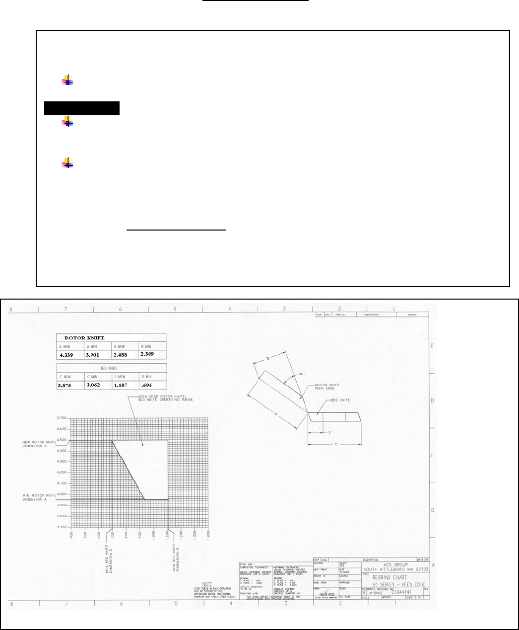
ROTOR KNIFE SHARPENING (Steep Angle Configuration)
The rotor knives must be sharpened to within 0.003" (0.076 mm) of each other. Greater dimensional
variations prevent the proper setting of the knife gap and may create other serious complications.
Grinding the cutting edge until it is free of nicks can be wasteful. It is not harmful to allow small
nicks to remain in the cutting edge.
WARNING!
Do not install rotor knives, which are smaller than the minimum dimension shown because the
fasteners, which secure these knives will interfere with the cutting circle. The rotor will not be able
to rotate and the bed knives will be damaged.
It is important to note that the minimum dimensions given for the rotor knife and bed knife
cannot be combined simultaneously to produce a cutting combination. The grinding charts shown
below and on the following page indicate the rotor knife and bed knife combinations that will work
for each type of rotor knife.
**EXAMPLE: A keen edge rotor knife with 3.901inch " A " dimension will work only with bed
knives which have "D" dimensions of .940 inch or greater.
*NOTE: Replacement knife sets and knife re-sharpening services are available from Sterling.
Contact the Customer Service De
p
artment at 800-641-3950 or 800-229-2919.