
Instruction Manual


Table Of Contents
- 2000 SERIES
- BP2042&BP2062 GRANULATORS
- COPYRIGHT 2006 ALL RIGHTS RESERVED PART NO. CI044120
- TABLE OF CONTENTS
- TABLE OF CONTENTS
- TABLE OF CONTENTS
- TABLE OF CONTENTS
- TABLE OF CONTENTS
- TABLE OF CONTENTS
- TOPIC/SECTION PAGE
- Cutting chamber access …………...…………………………………………..6-7
- Knife sharpening..………….…………………………………………………...6-9
- SECTION 7-TROUBLESHOOTING
- Overview………………………...……….……………………………….….…….7-1
- Test equipment
- Locating trouble
- Troubleshooting chart
- Processing faults..…………………………………………………………..………7-2
- Mechanical faults ………………………………………………………………….7-3
- Electrical faults…………………………………………………………………….7-4
- SECTI0N 8 -PARTS LISTS AND DRAWINGS
- INTRODUCTION
- MACHINE PARTS AND CONTROLS
- MACHINE PARTS AND CONTROLS
- MACHINE PARTS AND CONTROLS
- INSTALLATION
- INSTALLATION
- INSTALLATION
- INSTALLATION
- INSTALLATION
- INSTALLATION
- INSTALLATION
- SETTINGS AND ADJUSTMENTS
- SETTINGS AND ADJUSTMENTS
- SETTINGS AND ADJUSTMENTS
- SETTINGS AND ADJUSTMENTS
- SETTINGS AND ADJUSTMENTS
- SETTINGS AND ADJUSTMENTS
- SETTINGS AND ADJUSTMENTS
- SETTINGS AND ADJUSTMENTS
- SETTINGS AND ADJUSTMENTS
- SETTINGS AND ADJUSTMENTS
- SETTINGS AND ADJUSTMENTS
- SETTINGS AND ADJUSTMENTS
- SETTINGS AND ADJUSTMENTS
- SETTINGS AND ADJUSTMENTS
- SETTINGS AND ADJUSTMENTS
- SETTINGS AND ADJUSTMENTS
- SETTINGS AND ADJUSTMENTS
- SETTINGS AND ADJUSTMENTS
- SETTINGS AND ADJUSTMENTS
- SETTINGS AND ADJUSTMENTS
- OPERATION
- OPERATION
- OPERATION
- OPERATION
- MAINTENANCE
- MAINTENANCE
- MAINTENANCE
- MAINTENANCE
- MAINTENANCE
- MAINTENANCE
- MAINTENANCE
- MAINTENANCE
- MAINTENANCE
- MAINTENANCE
- MAINTENANCE
- MAINTENANCE
- TROUBLESHOOTING
- TROUBLESHOOTING
- TROUBLESHOOTING
- PARTS LIST AND DRAWINGS
- PARTS LIST AND DRAWINGS
- Rotor Positioning/Locking Assembly Drawing No.CI044115
- GA Non Sound Enclosed STERLING Drawing No.CI044063
- GA Non Sound Enclosed Hyd Opening STERLING Drawing No.CI044063-1
- GA Non Sound Enclosed Conveyor Feed STERLING Drawing No.CI044122
- Regrind Chart 10 Series – Steep Angle STERLING Drawing No.CI044141
- COPYRIGHT 2006 ALL RIGHTS RESERVED PART NO. CI044120
REVISION 9/04 BJF
49
SETTINGS AND ADJUSTMENTS
SECTION 4-19
Drive Belt Replacement Or Adjustment
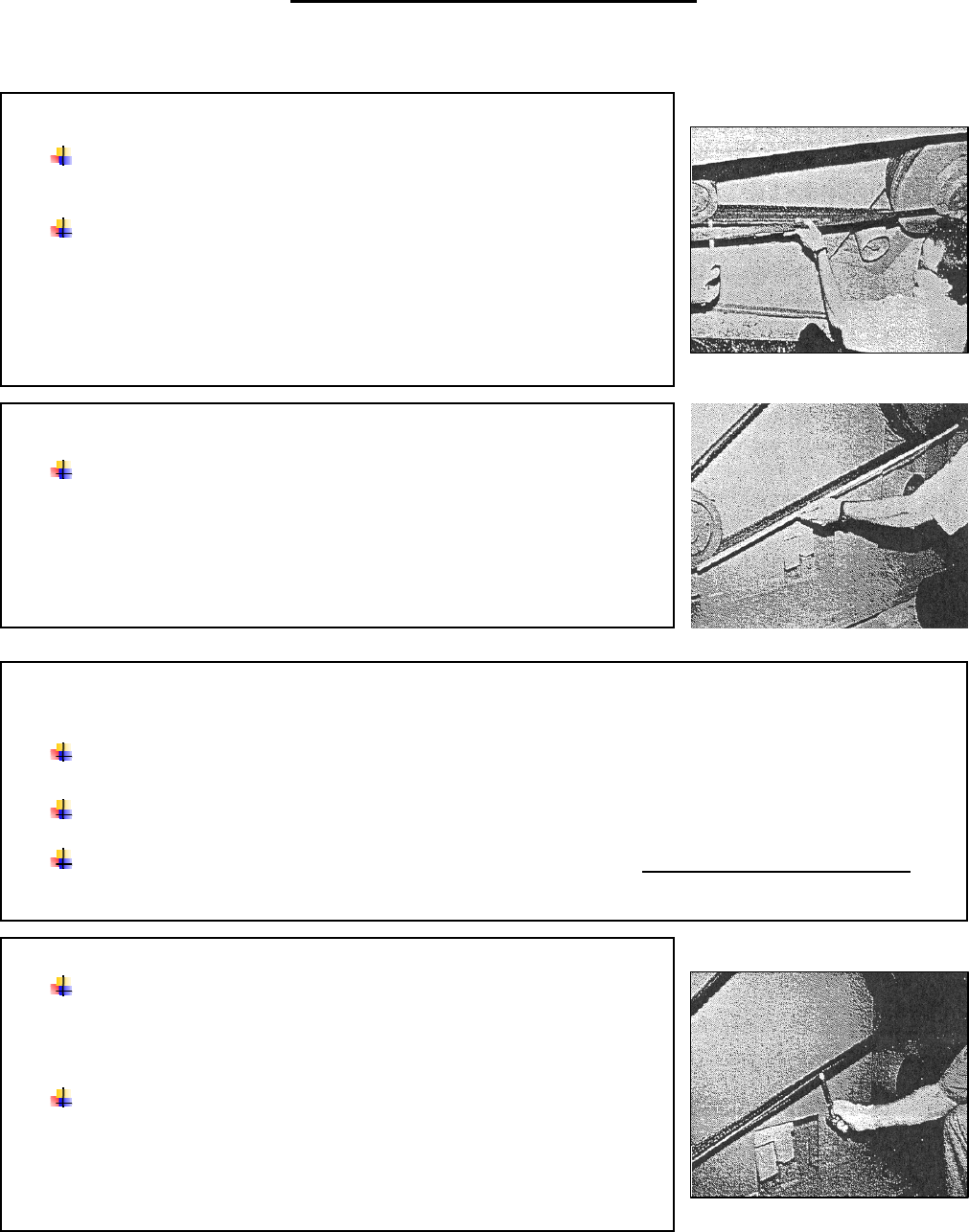
CHECK THE PULLEY ALIGNMENT
Tug outward on the pulleys to verify that they are tight on their
shafts.
Check the pulley alignment by holding a straight edge against the
edge of the large pulley and verifying that it is aligned with the edge of
the small pulley. If the edges of the pulleys do not align, perhaps
because the small pulley doesn't have as many grooves, use a tape to
measure from the straight edge to the belt on each pulley.
MEASURE THE BELT SPAN
Measure the belt span between the contact points on the large and
small pulleys as shown.
CALCULATE THE ALLOWABLE BELT DEFLECTION
The allowable belt deflection is obtained as follows.
Allowable belt deflection =Belt Span in inches (or mm) divided by 64
Another way to show that relationship: allowable belt deflection = Belt Span (in inches or mm)
64
MEASURE THE DEFLECTION FORCE
A gage to measure belt tension greatly facilitates this measurement.
You may purchase one from STERLING Engineering, or from the belt
manufacturer.
Use the belt gage to measure the force required to deflect the belt to
the allowable dimension.
*NOTE: Check the instructions supplied with the belt tension gage for
proper setting of the scales.