
Instruction Manual


Table Of Contents
- 2000 SERIES
- BP2042&BP2062 GRANULATORS
- COPYRIGHT 2006 ALL RIGHTS RESERVED PART NO. CI044120
- TABLE OF CONTENTS
- TABLE OF CONTENTS
- TABLE OF CONTENTS
- TABLE OF CONTENTS
- TABLE OF CONTENTS
- TABLE OF CONTENTS
- TOPIC/SECTION PAGE
- Cutting chamber access …………...…………………………………………..6-7
- Knife sharpening..………….…………………………………………………...6-9
- SECTION 7-TROUBLESHOOTING
- Overview………………………...……….……………………………….….…….7-1
- Test equipment
- Locating trouble
- Troubleshooting chart
- Processing faults..…………………………………………………………..………7-2
- Mechanical faults ………………………………………………………………….7-3
- Electrical faults…………………………………………………………………….7-4
- SECTI0N 8 -PARTS LISTS AND DRAWINGS
- INTRODUCTION
- MACHINE PARTS AND CONTROLS
- MACHINE PARTS AND CONTROLS
- MACHINE PARTS AND CONTROLS
- INSTALLATION
- INSTALLATION
- INSTALLATION
- INSTALLATION
- INSTALLATION
- INSTALLATION
- INSTALLATION
- SETTINGS AND ADJUSTMENTS
- SETTINGS AND ADJUSTMENTS
- SETTINGS AND ADJUSTMENTS
- SETTINGS AND ADJUSTMENTS
- SETTINGS AND ADJUSTMENTS
- SETTINGS AND ADJUSTMENTS
- SETTINGS AND ADJUSTMENTS
- SETTINGS AND ADJUSTMENTS
- SETTINGS AND ADJUSTMENTS
- SETTINGS AND ADJUSTMENTS
- SETTINGS AND ADJUSTMENTS
- SETTINGS AND ADJUSTMENTS
- SETTINGS AND ADJUSTMENTS
- SETTINGS AND ADJUSTMENTS
- SETTINGS AND ADJUSTMENTS
- SETTINGS AND ADJUSTMENTS
- SETTINGS AND ADJUSTMENTS
- SETTINGS AND ADJUSTMENTS
- SETTINGS AND ADJUSTMENTS
- SETTINGS AND ADJUSTMENTS
- OPERATION
- OPERATION
- OPERATION
- OPERATION
- MAINTENANCE
- MAINTENANCE
- MAINTENANCE
- MAINTENANCE
- MAINTENANCE
- MAINTENANCE
- MAINTENANCE
- MAINTENANCE
- MAINTENANCE
- MAINTENANCE
- MAINTENANCE
- MAINTENANCE
- TROUBLESHOOTING
- TROUBLESHOOTING
- TROUBLESHOOTING
- PARTS LIST AND DRAWINGS
- PARTS LIST AND DRAWINGS
- Rotor Positioning/Locking Assembly Drawing No.CI044115
- GA Non Sound Enclosed STERLING Drawing No.CI044063
- GA Non Sound Enclosed Hyd Opening STERLING Drawing No.CI044063-1
- GA Non Sound Enclosed Conveyor Feed STERLING Drawing No.CI044122
- Regrind Chart 10 Series – Steep Angle STERLING Drawing No.CI044141
- COPYRIGHT 2006 ALL RIGHTS RESERVED PART NO. CI044120
REVISION 9/04 BJF
43
SETTINGS AND ADJUSTMENTS
SECTION 4-13
Adjusting or Replacing Rotor Knives
CLEAN PARTS FOR REASSEMBLY
Clean the rotor knife seats with a stone or other non-
marring tool. Make sure that the backs of the knife seats are
clean so that the rotor knife can be placed squarely against
them.
Wipe the screws with lightly oiled cloth, do not leave an oil
film since lubrication can adversely affect the stress on a
screw installed to a fixed torque value.
ADJUST THE BED KNIVES
If the bed knives are installed, make sure that they are set back a sufficient amount to avoid
interference with the new or reground rotor knives.
MOUNTING SCREWS
DO NOT REPLACE THE MOUNTING SCREWS WITH ANY TYPE OF SCREW OTHER
THAN THAT SPECIFIED BY STERLING.
Substitution of improper screws could lead to premature failure, equipment damage, and serious injury
to personnel.
When regrinding the knives, you may re-use the same screws and washers but do not re-use them
more than six times. When installing new knives, replace the screws and washers with those furnished
by the factory.
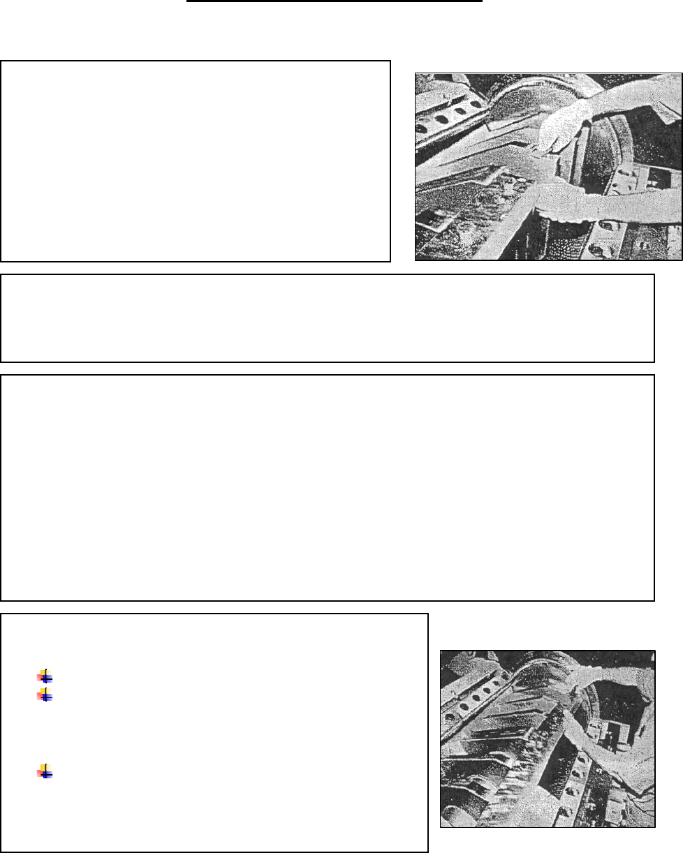
INSTALL THE NEW OR REGROUND ROTOR
KNIVES
Engage the rotor lock mechanism.
Place the first half rotor knife onto the rotor with the
beveled edge facing up and toward you This leaves the back-
side of the knife sitting squarely against the back of the knife
seat on the rotor.
Center the knife mounting holes over the rotor mounting
holes and install the screws. Tighten the screws finger- tight
while holding the knife snug against the back of the knife
seat.