
Instruction Manual


Table Of Contents
- 2000 SERIES
- BP2042&BP2062 GRANULATORS
- COPYRIGHT 2006 ALL RIGHTS RESERVED PART NO. CI044120
- TABLE OF CONTENTS
- TABLE OF CONTENTS
- TABLE OF CONTENTS
- TABLE OF CONTENTS
- TABLE OF CONTENTS
- TABLE OF CONTENTS
- TOPIC/SECTION PAGE
- Cutting chamber access …………...…………………………………………..6-7
- Knife sharpening..………….…………………………………………………...6-9
- SECTION 7-TROUBLESHOOTING
- Overview………………………...……….……………………………….….…….7-1
- Test equipment
- Locating trouble
- Troubleshooting chart
- Processing faults..…………………………………………………………..………7-2
- Mechanical faults ………………………………………………………………….7-3
- Electrical faults…………………………………………………………………….7-4
- SECTI0N 8 -PARTS LISTS AND DRAWINGS
- INTRODUCTION
- MACHINE PARTS AND CONTROLS
- MACHINE PARTS AND CONTROLS
- MACHINE PARTS AND CONTROLS
- INSTALLATION
- INSTALLATION
- INSTALLATION
- INSTALLATION
- INSTALLATION
- INSTALLATION
- INSTALLATION
- SETTINGS AND ADJUSTMENTS
- SETTINGS AND ADJUSTMENTS
- SETTINGS AND ADJUSTMENTS
- SETTINGS AND ADJUSTMENTS
- SETTINGS AND ADJUSTMENTS
- SETTINGS AND ADJUSTMENTS
- SETTINGS AND ADJUSTMENTS
- SETTINGS AND ADJUSTMENTS
- SETTINGS AND ADJUSTMENTS
- SETTINGS AND ADJUSTMENTS
- SETTINGS AND ADJUSTMENTS
- SETTINGS AND ADJUSTMENTS
- SETTINGS AND ADJUSTMENTS
- SETTINGS AND ADJUSTMENTS
- SETTINGS AND ADJUSTMENTS
- SETTINGS AND ADJUSTMENTS
- SETTINGS AND ADJUSTMENTS
- SETTINGS AND ADJUSTMENTS
- SETTINGS AND ADJUSTMENTS
- SETTINGS AND ADJUSTMENTS
- OPERATION
- OPERATION
- OPERATION
- OPERATION
- MAINTENANCE
- MAINTENANCE
- MAINTENANCE
- MAINTENANCE
- MAINTENANCE
- MAINTENANCE
- MAINTENANCE
- MAINTENANCE
- MAINTENANCE
- MAINTENANCE
- MAINTENANCE
- MAINTENANCE
- TROUBLESHOOTING
- TROUBLESHOOTING
- TROUBLESHOOTING
- PARTS LIST AND DRAWINGS
- PARTS LIST AND DRAWINGS
- Rotor Positioning/Locking Assembly Drawing No.CI044115
- GA Non Sound Enclosed STERLING Drawing No.CI044063
- GA Non Sound Enclosed Hyd Opening STERLING Drawing No.CI044063-1
- GA Non Sound Enclosed Conveyor Feed STERLING Drawing No.CI044122
- Regrind Chart 10 Series – Steep Angle STERLING Drawing No.CI044141
- COPYRIGHT 2006 ALL RIGHTS RESERVED PART NO. CI044120
REVISION 9/04 BJF
42
SETTINGS AND ADJUSTMENTS
SECTION 4-12
Adjusting or Replacing Rotor Knives
CARE IN HANLDING KNIVES
WARNING!
The rotor knives and bed knives are very sharp; therefore, it is imperative that you wear a pair of
heavy gloves to avoid injury.
Use the rotor locking mechanism to lock the rotor in the least likely position to cause you injury while you
work. The locking mechanism keeps the rotor from turning. A block of wood wedged around the rotor can
also be used to lock to rotor in place. If the rotor knives and bed knives are to be removed, remove the rotor
knives first and re
p
lace them last to reduce the chance of in
j
ur
y
.
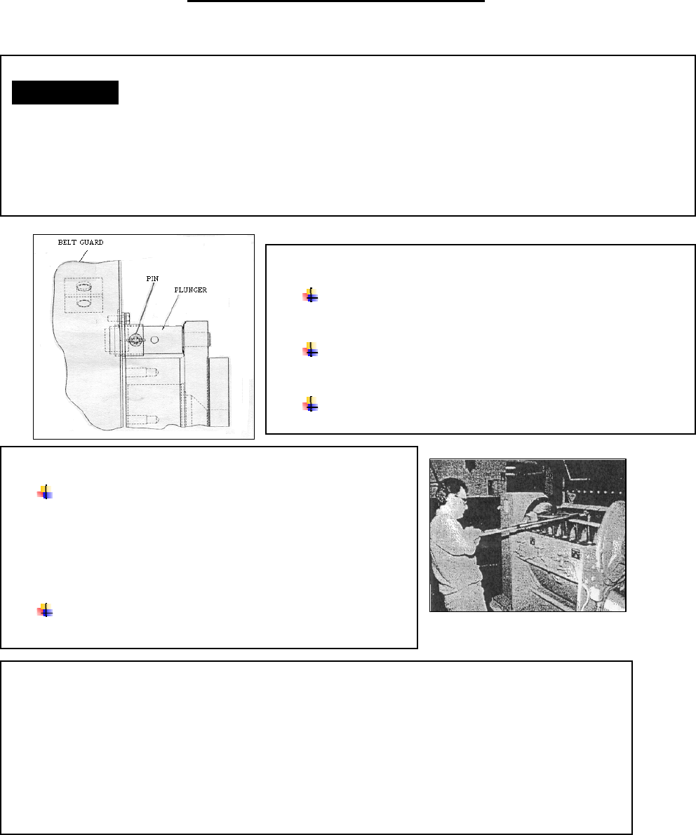
LOCK THE ROTOR
Locate the rotor lock mechanism on the left side of the
granulator, between the belt guard and bearing housing.
Pull the locking pin and rotate the plunger until it comes
in contact with the flywheel, locking the rotor position.
Re-install the pin to maintain locked position.
REMOVE THE MOUNTING SCREWS
Loosen the rotor knife screws with a 30 mm socket
mounted on a breaker bar (These screws are tightened to a
torque of 472 ft lbs (640 Nm) so make sure you have the
proper breaker bar (a four foot long (1.2 m) bar with a 3/4
inch (19 mm) drive is suggested. Make sure you have solid
footing while you apply the breaking force.
Remove the mounting screws from the right rotor knife
with a suitable socket wrench.
REMOVE THE ROTOR KNIVES
Lift the right knife off from the rotor and repeat the process with the left rotor knife.
Remove the rotor-locating pin, turn the rotor to bring the next knives into position for removal,
insert the locating pin to hold the rotor in this position. Repeat the process for the remaining
knives.