
Instruction Manual


Table Of Contents
- 2000 SERIES
- BP2042&BP2062 GRANULATORS
- COPYRIGHT 2006 ALL RIGHTS RESERVED PART NO. CI044120
- TABLE OF CONTENTS
- TABLE OF CONTENTS
- TABLE OF CONTENTS
- TABLE OF CONTENTS
- TABLE OF CONTENTS
- TABLE OF CONTENTS
- TOPIC/SECTION PAGE
- Cutting chamber access …………...…………………………………………..6-7
- Knife sharpening..………….…………………………………………………...6-9
- SECTION 7-TROUBLESHOOTING
- Overview………………………...……….……………………………….….…….7-1
- Test equipment
- Locating trouble
- Troubleshooting chart
- Processing faults..…………………………………………………………..………7-2
- Mechanical faults ………………………………………………………………….7-3
- Electrical faults…………………………………………………………………….7-4
- SECTI0N 8 -PARTS LISTS AND DRAWINGS
- INTRODUCTION
- MACHINE PARTS AND CONTROLS
- MACHINE PARTS AND CONTROLS
- MACHINE PARTS AND CONTROLS
- INSTALLATION
- INSTALLATION
- INSTALLATION
- INSTALLATION
- INSTALLATION
- INSTALLATION
- INSTALLATION
- SETTINGS AND ADJUSTMENTS
- SETTINGS AND ADJUSTMENTS
- SETTINGS AND ADJUSTMENTS
- SETTINGS AND ADJUSTMENTS
- SETTINGS AND ADJUSTMENTS
- SETTINGS AND ADJUSTMENTS
- SETTINGS AND ADJUSTMENTS
- SETTINGS AND ADJUSTMENTS
- SETTINGS AND ADJUSTMENTS
- SETTINGS AND ADJUSTMENTS
- SETTINGS AND ADJUSTMENTS
- SETTINGS AND ADJUSTMENTS
- SETTINGS AND ADJUSTMENTS
- SETTINGS AND ADJUSTMENTS
- SETTINGS AND ADJUSTMENTS
- SETTINGS AND ADJUSTMENTS
- SETTINGS AND ADJUSTMENTS
- SETTINGS AND ADJUSTMENTS
- SETTINGS AND ADJUSTMENTS
- SETTINGS AND ADJUSTMENTS
- OPERATION
- OPERATION
- OPERATION
- OPERATION
- MAINTENANCE
- MAINTENANCE
- MAINTENANCE
- MAINTENANCE
- MAINTENANCE
- MAINTENANCE
- MAINTENANCE
- MAINTENANCE
- MAINTENANCE
- MAINTENANCE
- MAINTENANCE
- MAINTENANCE
- TROUBLESHOOTING
- TROUBLESHOOTING
- TROUBLESHOOTING
- PARTS LIST AND DRAWINGS
- PARTS LIST AND DRAWINGS
- Rotor Positioning/Locking Assembly Drawing No.CI044115
- GA Non Sound Enclosed STERLING Drawing No.CI044063
- GA Non Sound Enclosed Hyd Opening STERLING Drawing No.CI044063-1
- GA Non Sound Enclosed Conveyor Feed STERLING Drawing No.CI044122
- Regrind Chart 10 Series – Steep Angle STERLING Drawing No.CI044141
- COPYRIGHT 2006 ALL RIGHTS RESERVED PART NO. CI044120
REVISION 9/04 BJF
40
SETTINGS AND ADJUSTMENTS
SECTION 4-10
Adjusting or Replacing Rotor Knives
BASIC FACTS ABOUT THE KNIVES
All of the rotor knives are ground in sets to equal dimensions. Mount and service them as sets.
The rotor knives must be mounted tightly against the backs of the knife seats in order to make it possible to
achieve consistent knife clearance.
Accurate cutting clearance is obtained by setting the bed knives to a 0.006 in. to 0.008 in. (0.15mm to
0.20mm) gap from the rotor knives.
The knives are adjusted by turning captive adjusting screws. For best results, start with the bed knives adjusted
to a wide gap from the rotor knife, and slowly adjust them to the required gap by turning the screws in the
same direction; avoid reversals. Reversals introduce inaccuracies due to backlash.
WORK SAFELY
WARNING!
TURN OFF AND LOCKOUT the power per OSHA 1910.147 OR ANSI Z244.1-1982
(Lock-out/Tag-out of Energy Sources).
If it is not possible to lock out the power, have an electrician remove the fuses.
Make sure the rotor has come to a complete stop.
Wear gloves to protect against injury from the rotor or bed knives.
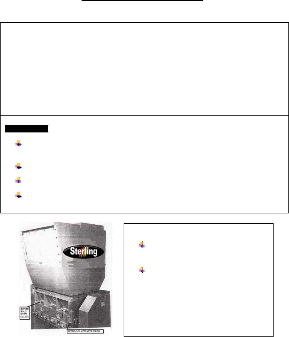
OPEN THE CUTTING CHAMBER
INTERLOCK
Disengage the interlock actuator screw with a
box wrench or a ratchet wrench.
Make sure the end of the interlock actuator
screw is visible and clear of any contact.
When disengaged, the interlock opens the electrical
control circuit to the motor and prevents the machine
from running.