
Instruction Manual


Table Of Contents
- 2000 SERIES
- BP2042&BP2062 GRANULATORS
- COPYRIGHT 2006 ALL RIGHTS RESERVED PART NO. CI044120
- TABLE OF CONTENTS
- TABLE OF CONTENTS
- TABLE OF CONTENTS
- TABLE OF CONTENTS
- TABLE OF CONTENTS
- TABLE OF CONTENTS
- TOPIC/SECTION PAGE
- Cutting chamber access …………...…………………………………………..6-7
- Knife sharpening..………….…………………………………………………...6-9
- SECTION 7-TROUBLESHOOTING
- Overview………………………...……….……………………………….….…….7-1
- Test equipment
- Locating trouble
- Troubleshooting chart
- Processing faults..…………………………………………………………..………7-2
- Mechanical faults ………………………………………………………………….7-3
- Electrical faults…………………………………………………………………….7-4
- SECTI0N 8 -PARTS LISTS AND DRAWINGS
- INTRODUCTION
- MACHINE PARTS AND CONTROLS
- MACHINE PARTS AND CONTROLS
- MACHINE PARTS AND CONTROLS
- INSTALLATION
- INSTALLATION
- INSTALLATION
- INSTALLATION
- INSTALLATION
- INSTALLATION
- INSTALLATION
- SETTINGS AND ADJUSTMENTS
- SETTINGS AND ADJUSTMENTS
- SETTINGS AND ADJUSTMENTS
- SETTINGS AND ADJUSTMENTS
- SETTINGS AND ADJUSTMENTS
- SETTINGS AND ADJUSTMENTS
- SETTINGS AND ADJUSTMENTS
- SETTINGS AND ADJUSTMENTS
- SETTINGS AND ADJUSTMENTS
- SETTINGS AND ADJUSTMENTS
- SETTINGS AND ADJUSTMENTS
- SETTINGS AND ADJUSTMENTS
- SETTINGS AND ADJUSTMENTS
- SETTINGS AND ADJUSTMENTS
- SETTINGS AND ADJUSTMENTS
- SETTINGS AND ADJUSTMENTS
- SETTINGS AND ADJUSTMENTS
- SETTINGS AND ADJUSTMENTS
- SETTINGS AND ADJUSTMENTS
- SETTINGS AND ADJUSTMENTS
- OPERATION
- OPERATION
- OPERATION
- OPERATION
- MAINTENANCE
- MAINTENANCE
- MAINTENANCE
- MAINTENANCE
- MAINTENANCE
- MAINTENANCE
- MAINTENANCE
- MAINTENANCE
- MAINTENANCE
- MAINTENANCE
- MAINTENANCE
- MAINTENANCE
- TROUBLESHOOTING
- TROUBLESHOOTING
- TROUBLESHOOTING
- PARTS LIST AND DRAWINGS
- PARTS LIST AND DRAWINGS
- Rotor Positioning/Locking Assembly Drawing No.CI044115
- GA Non Sound Enclosed STERLING Drawing No.CI044063
- GA Non Sound Enclosed Hyd Opening STERLING Drawing No.CI044063-1
- GA Non Sound Enclosed Conveyor Feed STERLING Drawing No.CI044122
- Regrind Chart 10 Series – Steep Angle STERLING Drawing No.CI044141
- COPYRIGHT 2006 ALL RIGHTS RESERVED PART NO. CI044120
REVISION 9/04 BJF
35
SETTINGS AND ADJUSTMENTS
SECTION 4-5
Adjusting or Replacing Bed Knives
CLEAN THE KNIFE MOUNTING SURFACES
Clean the knife mounting surfaces with a stone or
other non-marring tool and wipe them with a clean cloth.
Make sure they are free of all material, dust, and dirt.
MOUNTING SCREWS
DANGER!
DO NOT REPLACE THE MOUNTING SCREWS WITH ANY TYPE OF SCREW OTHER THAN
THAT SPECIFIED BY STERLING.
Substitution of improper screws could lead to premature failure, equipment damage, and serious injury to
personnel.
When regrinding the knives: you may re-use the same screws and washers, but do not re-use them more
than six times. When installing new knives, replace the screws and washers with those furnished by the
factory.
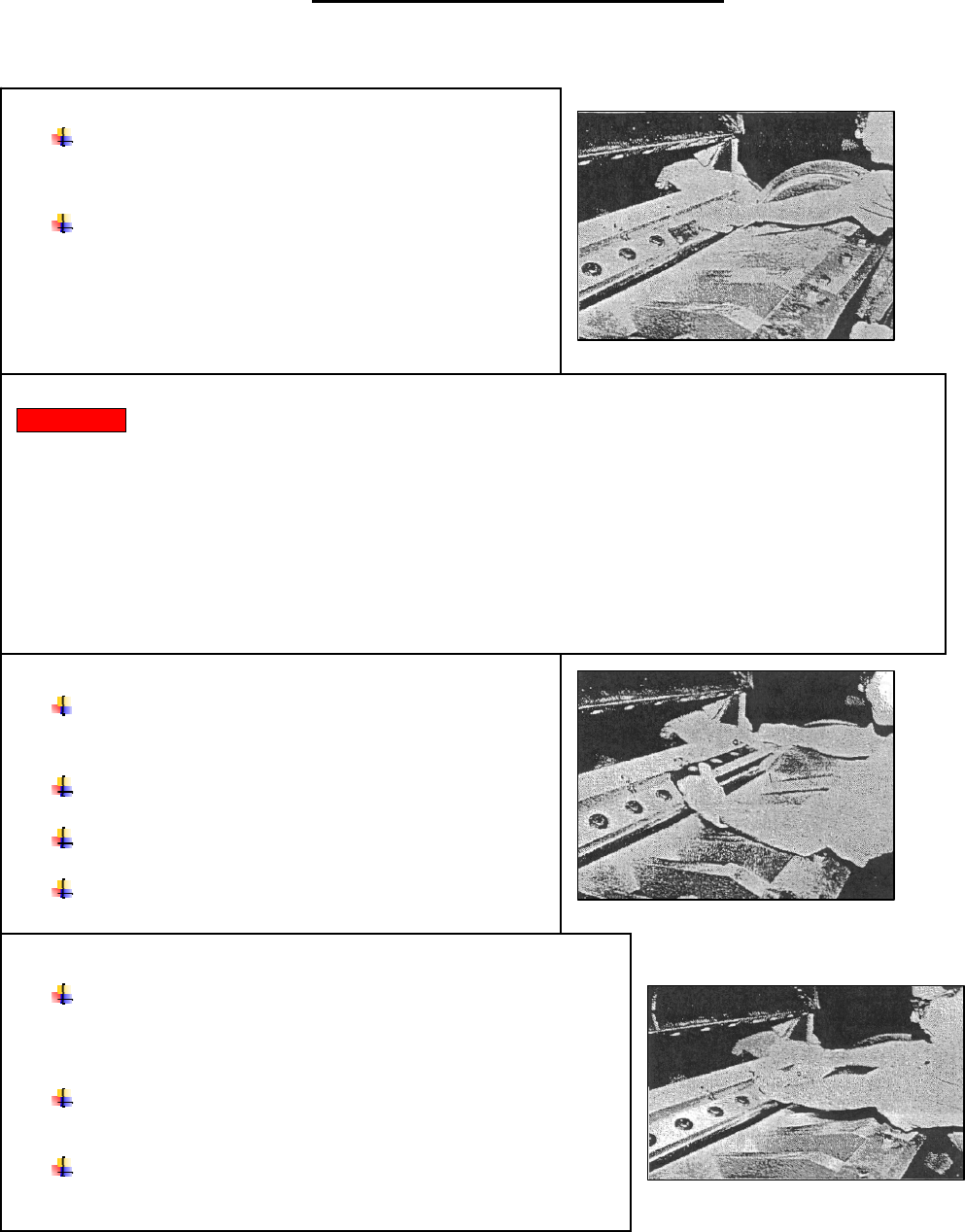
REPLACE THE UPSTROKE BED KNIFE
Wipe the screws with a lightly oiled cloth; do not
leave an oil film since lubrication can adversely affect the
stress on a screw installed to a fixed torque.
Install the upstroke knife making sure to install it
with the knife-edge on the lower side.
Back off the bed knife push screws at the rear of the
knife.
Repeat these steps for the second half of the knife.
REPLACE THE UPSTROKE KNIFE CLAMP
Place the clamp over one half of the knife and hold it in
position until you fasten the first two screws and washers finger-
tight.
Place the second clamp over the second half of the knife and
hold it while you fasten it.
Install the remaining mounting screws and washers and
tighten them finger-tight.