
Instruction Manual


Table Of Contents
- 2000 SERIES
- BP2042&BP2062 GRANULATORS
- COPYRIGHT 2006 ALL RIGHTS RESERVED PART NO. CI044120
- TABLE OF CONTENTS
- TABLE OF CONTENTS
- TABLE OF CONTENTS
- TABLE OF CONTENTS
- TABLE OF CONTENTS
- TABLE OF CONTENTS
- TOPIC/SECTION PAGE
- Cutting chamber access …………...…………………………………………..6-7
- Knife sharpening..………….…………………………………………………...6-9
- SECTION 7-TROUBLESHOOTING
- Overview………………………...……….……………………………….….…….7-1
- Test equipment
- Locating trouble
- Troubleshooting chart
- Processing faults..…………………………………………………………..………7-2
- Mechanical faults ………………………………………………………………….7-3
- Electrical faults…………………………………………………………………….7-4
- SECTI0N 8 -PARTS LISTS AND DRAWINGS
- INTRODUCTION
- MACHINE PARTS AND CONTROLS
- MACHINE PARTS AND CONTROLS
- MACHINE PARTS AND CONTROLS
- INSTALLATION
- INSTALLATION
- INSTALLATION
- INSTALLATION
- INSTALLATION
- INSTALLATION
- INSTALLATION
- SETTINGS AND ADJUSTMENTS
- SETTINGS AND ADJUSTMENTS
- SETTINGS AND ADJUSTMENTS
- SETTINGS AND ADJUSTMENTS
- SETTINGS AND ADJUSTMENTS
- SETTINGS AND ADJUSTMENTS
- SETTINGS AND ADJUSTMENTS
- SETTINGS AND ADJUSTMENTS
- SETTINGS AND ADJUSTMENTS
- SETTINGS AND ADJUSTMENTS
- SETTINGS AND ADJUSTMENTS
- SETTINGS AND ADJUSTMENTS
- SETTINGS AND ADJUSTMENTS
- SETTINGS AND ADJUSTMENTS
- SETTINGS AND ADJUSTMENTS
- SETTINGS AND ADJUSTMENTS
- SETTINGS AND ADJUSTMENTS
- SETTINGS AND ADJUSTMENTS
- SETTINGS AND ADJUSTMENTS
- SETTINGS AND ADJUSTMENTS
- OPERATION
- OPERATION
- OPERATION
- OPERATION
- MAINTENANCE
- MAINTENANCE
- MAINTENANCE
- MAINTENANCE
- MAINTENANCE
- MAINTENANCE
- MAINTENANCE
- MAINTENANCE
- MAINTENANCE
- MAINTENANCE
- MAINTENANCE
- MAINTENANCE
- TROUBLESHOOTING
- TROUBLESHOOTING
- TROUBLESHOOTING
- PARTS LIST AND DRAWINGS
- PARTS LIST AND DRAWINGS
- Rotor Positioning/Locking Assembly Drawing No.CI044115
- GA Non Sound Enclosed STERLING Drawing No.CI044063
- GA Non Sound Enclosed Hyd Opening STERLING Drawing No.CI044063-1
- GA Non Sound Enclosed Conveyor Feed STERLING Drawing No.CI044122
- Regrind Chart 10 Series – Steep Angle STERLING Drawing No.CI044141
- COPYRIGHT 2006 ALL RIGHTS RESERVED PART NO. CI044120
REVISION 9/04 BJF
21
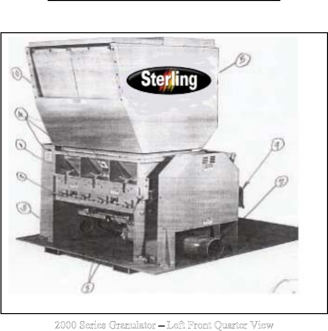
MACHINE PARTS AND CONTROLS
SECTION 2-1
1. Hold-down clamps - cutting chamber
2. Screen cradle retainers
3. Interlock actuator screw – cutting chamber
4. Safety plates
5. Feed hopper
6. Rotor bearing housing (Not shown)
7. Discharge duct (Optional mount to either side)
8. Start/Stop pushbuttons located on the electrical cabinet, not shown (Cabinet is option
equipment)
9. Hopper opening screw jack
10. Drive guard
11. Hopper flap
12. Rotor lock mechanism (Between guard and chamber)
The 2000 series granulators have a common cutting diameter of 20” (500mm) and a common
throat size of 20” (500mm) by widths ranging from up to 62” (1575mm). They are designed for
reclamation of large blow-molded and thin walled injection molded parts, films and fibers.
The machines in the 2000 Series can be fitted with screens having hole sizes to suit the particular
application. The 2000- Series machines conform to ANSI Standards: B151.11 and NFPA 79.