A3 System Management Software Software Manual Bulletin number: BF4-600.2 Part number: 882.00278.00 Date: 11.14.2008 Sterling 2900 S. 160th Street New Berlin, WI 53151 Tel: [262] 641-8610 Fax: [262] 641-8653 www.sterlco.
Confidential Supervisory Manual Not to be released to floor operators Table of Contents Overview .......................................................................................................................................................................4 Frequently Asked Questions .........................................................................................................................................7 Installing A3..................................................................
Preface The information in this manual is based on current industry sources and believed by the author to be correct and as complete as possible at the time of printing. It is possible that later changes have been made by the manufacturers of ACS equipment and are not included in this publication. Although every effort has been made to insure total accuracy, ACS cannot assume any liabilities for omission, errors or changes that have occurred in the production of this manual.
Overview The A3 System Management Software program is a Windows based program that allows you to control and monitor up to 1000 ACS devices.
• Built in Job Report Manager that allows the operator to generate reports based on jobs rather than time. The Job Report Manager keeps track of job numbers, material reference numbers, material lot numbers, and material silo numbers for each hopper on every configured device. The operator can select to start or stop the job at any time.
Who should use this manual Use this manual if you are responsible for system integration of machinery in your facility. You should have a basic understanding of Allen Bradley or Mitsubishi PLC, Ethernet networking, and Windows XP. If you do now, contact the appropriate personnel to obtain information before proceeding. Your IT personnel or outside networking consultants should be involved in the installation of this software package.
Frequently Asked Questions • How many units can A3 integrate? 1000 units, which 255 can be the older proprietary units. • What minimum software version do I need to have on blenders and weigh hoppers in order to communicate with A3? ACS Allen Bradley Batch software-> 3.2 ACS Mitsubishi Batch software-> 1.2 Older Proprietary HydReclaim OS/OA software -> 700A Older Proprietary HydReclaim OFC software -> 5.5A Older Proprietary HydReclaim OL software -> 10.
if you don’t already have a LAN in your facility you will need to add one by purchasing an Ethernet Hub or Switch from any store that sells Ethernet equipment. For older HydReclaim OS/OA/OL/OFC equipment you will need a 2-twisted pair shielded cable such as Belden 8103 or similar. You will also need a DB9Male solder type for each device and a DB9 Female solder type for the PC, as well as hoods for each connection.
What’s new in version 1.1 Job Report Manager Now you can generate reports on demand instead of just time. Along with this comes the new feature of Job Management that allows the operator to enter in the following data into the job: • Job Number • Material reference numbers for each hopper • Material lot numbers for each hopper • Material silo numbers for each hopper The operator can start or stop a job at any time. The reports that generate are date, time, and job number stamped for easy recording.
What’s new in version 2.0 Sterling SGB Communications Driver Now you can communicate with any SGB blender. The limitations are the same as the with the AEC OS/OA blenders. Up to 1000 units can be networked over an Ethernet network. The system can also communicate with both the AEC units and the Sterling units at the same time over the same network cable. What’s new in version 4.
Chapter 1 Installing A3 This chapter explains how to install A3 from your CD to your hard drive. • System requirements • Step-by-step installation instructions • Starting and exiting A3 software Overview A3 software installs directly from the CDROM to your hard drive. The CD also contains the “Windows XP Service Pack 1”, drivers for the USBRS422/485 Legacy module (required when integrating older proprietary equipment), Internet Explorer 6.0 upgrade, and this manual.
Installing A3 Before you start the installation you will need to be logged in as the administrator and you will need to close all programs that are running. Checking your PC: You should first check that your PC meets the requirements.
Step 2: Examine the above and ensure that you see Microsoft Windows XP, Service Pack 1, at least 750MHZ, and at least 128MB or RAM.
Step 2: Click on “(C:) and examine “Free Space” in the lower left corner under “Details”. It should be at least 30 GB. You should also see that you have a working CDROM drive on this page. If the system meets all of the requirements except the “Service Pack 1” requirement” then you will need to install the Windows XP Service Pack 1 from the A3 CD.
Installing A3: Insert the A3 CD into the CDROM drive. The installation software will automatically start. If it doesn’t, then run Setup.exe from the A3 CD.
Step 2: Click the picture of the computer Step 3: Click Continue Page Number 16
Step 4: Success, Click “OK” to complete.
Starting and exiting A3 To start A3: 1. From the Start menu, click Programs. 2. Select ACS Software and click A3 System Management Software. To exit A3: Click Exit from the File Menu.
Configuring the PC If your PC is part of your plants LAN then you will need to have your system administrator configure the IP settings for the PC.
Step 2: Right click on your Local Area Connection and select “Properties” Step 3: Double Click on “Internet Protocol (TCP/IP)” Page Number 20
Step 4: Set your screen to look like this, then click OK, and OK again. Remember that you need to have a unique IP for all of your blenders and for the PC. For example you could use the following scheme: PC IP -> 192.168.0.1 Blender 1 IP -> 192.168.0.10 Blender 2 IP -> 192.168.0.11 Blender 3 IP -> 192.168.0.
Running the Cables and Hardware to interconnect they system Depending on your expertise and preference you can either purchase CAT5 cables to length with the connectors already attached to both ends. This makes it somewhat difficult to get the connector into the blender panel because of the head on the cable, but not impossible. Either way you will need to have some sort of Hub, Switch, or Router to interconnect all of the blenders with the PC.
Sample network.
Networking instructions for the ACS Allen Bradley batch blender Installing the PLC hardware The first step is that you must install the Ethernet module and cable into every PLC. You will need an Ethernet Module (A0563939, 1761-NET-ENI) and a Cable for the Module (A0565898, 1761-CBL-AM00) per blender. The module snaps in to the DIN rail just to the right of the Mixer Motor contact and the cable snaps into the module and PLC: You will also need to make sure that you are running at least 3.
Configuring the PLC You will need to go to Network Setup found under “Setup” on the blender and set the appropriate IP address. The SUBNET mask should be set to “255.255.255.0”. Make sure the Ethernet Configurator is enabled: Step 1: touch the AEC icon and enter your password Step 2: touch “Network Setup” Step 3: set appropriately What is an IP address An IP address is a unique address for each device that is on your network. The number can be any number other than 0.0.0.0. Some examples are “192.168.0.
Networking instructions for the older proprietary Hydreclaim embedded equipment Installing the required USB RS422/485 adapter on the PC The installation is very easy. 1. Remove the USB adapter from the box and plug it into a free USB port on the PC. 2. Windows will find the hardware automatically, keep clicking next until you see “finish”. Windows will find 2 separate items when you plug the adapter in, so you will have to repeat this step a few times until it says that your new hardware is ready to use.
The pin outs for the cables are as follows: PC PIN9 PIN1 PIN2 PIN3 to 1st BLENDER PIN4 PIN5 PIN8 PIN9 BLENDER to BLENDER PIN4 PIN4 PIN5 PIN5 PIN8 PIN8 PIN9 PIN9 It is best to ring out every pin on every connector to ensure that it is wired correctly and that there aren’t any shorts prior to connecting the cables to each blender. Damage to your blenders can occur if you’ve wired this incorrectly.
Networking instructions for the ACS Mitsubishi batch blender Installing the PLC hardware The first step is that you must install the Ethernet module and cable into every PLC. You will need the Mitsubishi FX2N-232-BD board added to each blender, an Digi One IA Ethernet Module (Digi p/n:70001862), and a 3 foot DB9 Null Modem Cable that is female on both ends (BlackBox.com p/n EYN257H-0006-FF) per blender.
Networking instructions for the Maguire WSB Blender Installing the PLC hardware The first step is that you must install the Ethernet module and cable for every blender. *Ethernet Module ACS Part # 724.00872.00 (Digi One SP) *Ethernet Module Wall Mount ACS Part # 724.00873.00 *Module Cable ACS Part # A0565856 (10' DB9F-DB9F straight cable) This module should be mounted to either the blender frame or a nearby structure using the purchased Wall Mount.
Configuring the Digi One IA or Digi One SP Ethernet Modules The first thing to complete is configuring the PC for Ethernet. Configuring the PC If your PC is part of your plants LAN then you will need to have your system administrator configure the IP settings for the PC.
Step 2: Right click on your Local Area Connection and select “Properties” Step 3: Double Click on “Internet Protocol (TCP/IP)” Page Number 31
Step 4: Set your screen to look like this, then click OK, and OK again. Remember that you need to have a unique IP for all of your blenders and for the PC. For example you could use the following scheme: PC IP -> 192.168.0.1 Blender 1 IP -> 192.168.0.10 Blender 2 IP -> 192.168.0.11 Blender 3 IP -> 192.168.0.
Running the Cables and Hardware to interconnect the system Depending on your expertise and preference you can either purchase CAT5 cables to length with the connectors already attached to both ends. This makes it somewhat difficult to get the connector into the blender panel because of the head on the cable, but not impossible. Either way you will need to have some sort of Hub, Switch, or Router to interconnect all of the blenders with the PC.
Before the modules can be used they each need to be programmed with the IP Address. You will need to have the module wired to 24VDC if it is DIN rail mount or plugged into the wall receptacle if a wall transformer has been provided. You must also connect the module to your Ethernet network. If you have a separate 24VDC power supply you can program these modules without installing them into the blender and they will retain the programmed address. Locate and install the CD that came with your Ethernet module.
This will be shown until the software finds the attached module. Double click on the unit you wish to program.
Configure the IP as shown above (remember that the last digit in the IP must be unique for each blender, here that digit is shown as “11”. Be sure that no other blender is using “11” before proceeding.
Click Incoming Network Connection then next Click TCP Sockets then next Page Number 37
Configure the baud rate to 19,200 for ACS Mitsubishi blenders.
From this screen click Next to save the configuration to the Ethernet module The configuration will begin to be saved and then the system will reboot the Ethernet Module. This takes about a minute. Deselect Register and click Finish to complete.
Chapter 2 Using A3 A3 software uses menus, windows, status bars, and right click menus as do most Windows applications.
Tip of the day The application window will appear and will show you a “Tip of the Day”: Deselecting “Show Tips at Startup” will prevent the “Tip of the Day” from appearing the next time the program starts.
many random tips by hitting “Next Tip”. Hitting “OK” will close the Tip dialog.
Drop down menus A3 has many drop down menus that can be selected: Page Number 43
Page Number 44
Page Number 45
Right click menus A3 also uses right-click menus. These right-click menus are all accessible from the dropdown menus listed above, but right-clicking is sometimes quicker and easier. Right-clicking in the blank white area will bring up these.
Right-clicking on a device will bring up these. Right-clicking on the sheet name will bring up these.
Status Bar on A3 The status bar is located near the bottom of the A3 main page: The status bar on the left shows when the next automatic report will generate, the bar in the middle always shows the date and time, and the bar on the right shows the countdown for the automatic report.
Customizing A3 The A3 layout can be modified by the user. The following are some of the customizable features: • The Customer Name can be configured by selecting “File/Customer Name”. Once changed the customer’s name will appear in brackets on the title bar.
• The Sheet Name can be modified by selecting “File/Edit Sheet Name”. Once changed the name of the sheet (“Plant Name”) will be changed to whatever the user has selected. Commonly this is the location of the plant (i.e. Dayton, OH).
• Adding multiple sheets to the system. A3 is capable of having up to 20 different sheets with up to 50 devices on each sheet. To add a sheet select "File/New Sheet”. To delete a sheet click on the sheet and then select “File/Delete Sheet”.
A3 options The A3 software also has many preference options that can be changed by the user.
Verify Action Options These options enable or disable the “Are you sure…” prompts after certain operations. Hard Drive Options This option allows the user to configure the minimum allowed hard drive space to allow saving. The minimum value that can be entered here is 2000 MB (2 GB). Security Options These options enable or disable password protection on certain operations. Once password protection is enabled the operator must enter in the user password in order to perform the operation.
Chapter 3 Application Screens A3 software has many screens that can be accessed: • Virtual Control Panel for each unit. This is used to start or stop the unit and to monitor the current recipe and inventories. • Alarm Log for each unit. This is used to view the alarm history of each device. • Change Recipe Page. This is used to change the running recipe of a device • Recipe Book. This is used to store recipes for later recall by an operator. • Batch Data Page for each unit.
Virtual Control Panel The virtual control panel is accessed by double clicking on the icon of the blender from the main page.
Blender Name and Software Version Recipe Entry Mode Push to change recipe Push to go to Recipe Book Current Recipe Values Current Inventory Push to Accept New Recipe Push to clear the inventory Push to go to the Alarm Log Push to go to the Batch Log Indicates running or stopped Current Active Alarms Push to start or stop blender The Virtual Control Panel.
Blender Name and Software Version You can operator the buttons as if you were in front of the real control Strobe Flashes during Alarm Thumbwheels update as operator changes the recipe Current Recipe Current Inventory Push to clear the inventory Current Alarms The Virtual Control Panel for Maguire Blenders.
Blender Name and time of log Alarm History (up to 1000 alarms per blender) Push to clear the log Click to send log to the printer Click to save the log to a specific location The Alarm Log Click to go back to Virtual Control Panel Change Recipe Page. Enter new values and hit “Load” or cancel to quit. If a box shows “******” then this is the automatically calculated entry and does not need to be entered.
If the recipe is not correct an error message will be given that will prevent it from loading.
Total not 100% error message Page Number 60
The following are error messages given when using the older proprietary blenders: Recipe Not Totaling 100% Page Number 61
The following is the successful message given when using the older proprietary blenders: Recipe Transferred message Page Number 62
Recipe Book.
Batch Data Page. The Batch Data Page shows the actual weight of every component of every batch made (up to 5000 batches). Clicking on the “Show these Hoppers” boxes only effects what is displayed and does not effect the data in the log. The graph is automatically scaled for the hoppers you have chosen to be displayed. To reload the graph click “Refresh”.
Uptime Data Page The Uptime Data page is accessed by selecting “View/Uptime Data…” from the drop down menu. This data shows the percentage of time that each blender has been in the “Run” mode and is useful in seeing the overall proficiency of each machine.
SCADA Scan Times Page The SCADA Scan Times Page is accessed by selecting “View/SCADA Scan Times” from the dropdown menu. The display is in seconds and is rounded to the nearest whole second. These numbers represent how long it takes for each device to poll all of the configured parameters. This time can be dramatically increased or decreased by enable or disabling features for each device (see “Working with A3 Device Objects” for more details).
Memory Status Page. The Memory Status Page is accessed by selecting “View/Memory Status” from the dropdown menu. This page is useful in determining the amount of memory you have consumed with the current configuration and is also useful when configuring systems with up to 1000 devices. The most important item to look at is the first one, “Percent of Memory Used”. This should be under 60% for Windows to remain stable.
Data Parameters Page The Data Parameters Page is accessed by selecting “View/Data Parameters” from the dropdown menu. This page shows all of the available data parameters for each device. The status of each of these items is automatically configured when you enable or disable features for the selected device (see “Working with A3 Device Objects” for more details). This page is here strictly for customers who wish to develop there own SCADA package.
Chapter 4 Working with A3 Device Objects This chapter explains: • What is an A3 Device Object • Adding new A3 Device Objects • Editing A3 Device Objects • Deleting A3 Device Objects Overview The A3 system is used to display and control many objects (up to 1000). A3 Device Objects are the heart of the system and are easy to add and edit. What is an A3 Device Object? An A3 Device Object is any blender or weigh hopper that you are adding to the A3 communications package.
Adding new A3 Device Objects Simply right click in the blank white area of the sheet you wish to add a device to and select “Add ACS Device”. You will then see the following dialog: Add New Device Dialog 1. Edit the Device Name. Use whatever is appropriate for your blender. 2. Edit Device Description if desired. Any text that is entered here will “pop-up” when the operator holds the mouse over the icon for the device.
Configuring a ACS Allen Bradley Batch Blender Device When selecting a newer AB OS/OA device you will also need to enter in the IP Address for the blender. This IP is a fixed IP and must be unique for every device that resides on the same LAN (Ethernet Network). Some examples are: “192.168.0.10”, “192.168.0.1”, “192.168.0.2”, etc. You will also need to program the blender with the same IP address.
You will also need to set the SUBNET MASK for the blender. This needs to be set to “255.255.255.0”. Once configured you will need to make sure you have connected the Ethernet Module and Cable (see “Networking instructions for the newer AB OS/OA Blender” for details). Finally, touch “Send Ethernet Config to Module” and monitor the Ethernet module on the blender.
Here are some quick trouble shooting answers: • Power light on module is off: Check that the “Cable/External” switch is set to “Cable” and that you are using the correct cable (see “Networking instructions for the newer AB OS/OA Blender”). The module gets power from the PLC. • Fault light on module is on: Check to ensure that the DCOMM light on the PLC is on, if not you need to enable DCOMM by removing the snap cover on the PLC and holding in the COMMS button.
Configuring an Older Proprietary OS/OA, OL, or OFC that uses an embedded controller (not a PLC): Limitations with using the Maguire WSB Batch Blender: • target vs. actual batch data is not available • alarm name and logging is not available These are limitations with the Hynet protocol and blender functionality and not A3.
Step 1: From the main menu hit “5” and enter in your password.
Step 4: hit “1” or “2” to increase or decrease Serial ID, then Backup Step 5: hit “1” or “2” to change Baud Rate, then Backup The SERIAL SETUP section is the same for all proprietary devices on the network (changing the settings here means changing it for all devices). The COM Port should be set to whatever the USB RS422/485 is set to.
Step 1: click start, right-click on “My Computer”, then click “Properties” Step 2: Click the “Hardware” tab and then click “Device Manager” Page Number 77
Step 3: Expand the “Ports” and observe the Kontron Port # If you do not see the Kontron entry then see “Networking instructions for the newer AB OS/OA Blender”.
Configuring an ACS Mitsubishi Batch Blender Device: When selecting “SGB Blender” under Device type you will be given a few extra entries to complete: Page Number 79
Configuring a Maguire WSB Batch Blender Device: When selecting “Maguire WSB” using Device Type you will be given a few extra entries to complete. You will need to select the features you want as well as configure how many hoppers to show: Limitations with using the Maguire WSB Batch Blender: • recipe can be monitored, but not controlled • target vs. actual batch data is not available These are limitations with the Maguire protocol and blender functionality and not A3.
Checking the Device your about to Add Once you’ve configured your device you will be ready to hit “OK” on the “Add a New Device…” dialog. Before the device is added an automatic check is performed to see if the device is responding correctly.
You should click “No” unless you know that the device is not hooked up (your setting up the system before the network is in place).
Device States Each icon has different states to indicate the conditions of the device: Device is communicating and is not in the “Run” mode. Device is in the “Run” mode. This state flashes. Device has an alarm active at the unit. Device is not communicating with A3. Editing an existing device Right click on the device and select Edit. If you make changes hit OK when done. Deleting a device Right click on the device and select Delete Device.
Chapter 5 Working with the A3 Recipe Book This chapter explains: • What is the A3 Recipe Book • Accessing the Recipe Book • Creating Stored Recipes • Viewing a stored recipe • Editing existing Stored Recipes • Deleting Stored Recipes • Printing the Recipe Book • The location of the Recipe Book • Loading a stored recipe into a device Overview This chapter will help you understand how to use the A3 Recipe Book.
Accessing the Recipe Book The recipe book can be accessed by selecting “Tools/Recipe Book” using the dropdown menu or can be accessed by double clicking on a device and from the “Virtual Control Panel” clicking “Recipe Book”.
Creating a stored recipe 1. Edit the RECIPE DATA fields to appropriate values. 2. Click “Save New” and enter in a name in the “File Name” box and click Save.
Editing Existing stored recipes 1. Click on an AVAILABLE RECIPE and the RECIPE DATA fields will show the values for the recipe you’ve selected. 2. Edit the RECIPE DATA fields. 3. Click “Save New” and select the stored recipe and click Save. Deleting stored recipes To delete a single recipe: 1. Click on an AVAILABLE RECIPE. 2. Click “Delete” and the recipe will be removed. To delete all of the recipes: 1. Click “Delete All” and all stored recipes will be removed.
Loading a stored recipe into a device • Access the Virtual Control Panel by double clicking on the device from the main page. • Click on “Recipe Book”. • Click on the “AVAILABLE RECIPE” that you want to load. • Click “Load” • Click “Accept Recipe” and the recipe will be loaded (only on the Newer AB OS/OA blenders, the recipe is already loaded at this point for the Older Proprietary blenders). If the recipe is not correct an error message will be given that will prevent it from loading.
Total not 100% error message Page Number 89
The following are error messages given when using the older proprietary blenders: Recipe Not Totaling 100% Page Number 90
The following is the successful message given when using the older proprietary blenders: Recipe Transferred message Page Number 91
Chapter 6 Working with the Report Manager This chapter explains: • What is the Report Manager • Accessing the Report Manager • Automatic vs. Manually generated reports • Configuring what is included in the reports • Saving the reports • Auto Clear Features • Using Manually generated reports (Job Report Manager) • Sample Reports using Automatic Generation • Sample Reports using Manual Generation (Job Reports) Overview This chapter will help you understand how to use the A3 Report Manager.
What is the Report Manager The A3 Report Manager is a utility that allows the user to generate reports for each device that contain: • Inventory Usage information • Uptime Percentage information (the percent of time that the device has been in the “Run” mode) • Alarm Log information (stores up to 1000 of the device’s alarms) • Recipe Info Log (stores up to 1000 recipe changes along with the recipe values and the inventory when the recipe was started) • Batch Data information (the actual weight of every comp
Automatic vs. Manually generated reports The report manager can be configured to either automatically generate reports based on a time interval (from 1-8760 hours) or manually generate reports based on “Jobs”. This option is up to the user and can be configured using the following: Frequency of Reports Automatic reports are usually used when the user runs the same product on their lines or are not concerned with documenting each product run.
Configuring what is included in the Reports The user can select what information will be included in each report by enabling or disabling the following check boxes (also what is cleared): Report Options You should select to have all reports automatically clear and restart so that the system does not exceed the limitations of each report size. The system can accumulate the following: • Up to 999,999,999 Lbs or Kgs of total inventory for each device.
Saving the reports The user can specify the location where all reports will be saved using the following: Saving the Reports To select the location click “Select Directory”, go to the desired directory, and then click “Save”. The path will automatically be calculated for you.
Using Manually generated Reports (Job Report Manager) First step is to create the System Inventory Resin Database.
To access double click on the icon of the device from the main page, then click on “Job Report Manager”: Click to Start a Job, Inventories and logs will clear at this point Job Number Material Information for Job that will be saved with the report Click to Finish a Job, be sure to enter in all of the data first.
Sample Reports using Automatic Generation All of the selected reports will be saved in the path selected under the Report Manager. The name of the report will be date & time stamped for reference.
Automatically generated reports The date and time stamp is as follows and cannot be changed: Year_month_day_hour(in military time)_minutes_seconds This is followed by the name of the device and the name of the log.
Sample Reports using Manual Generation (Job Reports) All of the selected reports will be saved in the path selected under the Report Manager. The name of the report will be date, time, and job number stamped for reference. Below are some sample report: Manually generated reports (in blue) The date, time, and job number stamp is as follows and cannot be changed: Year_month_day_hour(in military time)_minutes_seconds JOB_job # This is followed by the name of the device and the name of the log.
Sample Reports Here are some sample reports.
Alarm Log (same for auto or manual, just name would be different) It is important to note that whenever the inventory is cleared either at the blender or the PC an entry of what the inventory was prior to clearing is added. If the data in the inventory and uptime report is short of what you expect then check the alarm log for the device to see if the inventory was cleared sometime into the report.
Recipe Info report (same for auto or manual, just name would be different). This log is generated every time the operator changes the recipe. Once a recipe change is detected this log records the inventories and recipe just prior to the change.
Batch data report (same for auto or manual, just name would be different) Page Number 105
Chapter 7 Working with the configuration file This chapter explains: • What is the configuration file • Setting the system back to defaults • Saving the configuration • Opening a previously saved configuration file • The location of the configuration file Overview This chapter will help you understand how to manage the A3 configuration file. What is the configuration file The configuration file is a file that is used by A3 to remember your preferences and settings.
Setting the system back to defaults The system can be set back to the original defaults by selecting “File/Set Config to Default” from the dropdown menu. This should be used with caution. Saving the configuration The configuration file is automatically saved when you exit the program, but in the case the power is removed from the computer the configuration file will not be saved. For this reason it is a good idea to save the configuration from time to time when you are configuring large systems.
Chapter 8 Working with the A3 System Log file This chapter explains: • What is the A3 System Log file • What is logged in the file • The location of the file Overview This chapter will help you understand how to use the A3 System Log. What is the A3 System Log file The A3 System Log File is history log of system level alarms and operations performed by the user. It is not necessary to view this log except when trouble shooting the A3 system.
What is logged in the file • • • • • • Any communications error (time of alarm and time cleared). Time the program was started Time the program was stopped Printer error messages Setup operations performed by the user Time of automatic and manually generated reports The A3 System Log It is normal that when the program is started you will see communication alarms for several devices. This is normal while the devices are initializing and as long as the alarms clear quickly you should not be concerned.
The location of the file The A3 system log file is always named “a3_system_log.txt” and is located in the installation path. By default the file will be found in “c:\program files\a3 system management software\ a3_system_log.txt” and can be as large as 5 MB in size depending on the number of entries.
Chapter 9 Troubleshooting This chapter explains: • How to trouble shoot a software installation problem • How to trouble shoot a PC problem • How to trouble shoot a communications problem • Where to go for further help Overview This chapter will help you understand how to properly trouble shoot the A3 System Management Software.
How to trouble shoot a software installation problem Problem During the installation of the A3 software you receive a message saying that some of the files on your PC need to be updated and then asks you to reboot. After rebooting and running the installation again you receive the same message. Solution The problem is that your PC does not have Windows XP Service Pack 1 installed. This is an update from Microsoft and must be installed first. See “Chapter 1 Installing A3” for a detailed solution.
How to trouble shoot a PC problem Problem Your software installation went fine, but your PC crashes intermittently. Solution A3 software has been testing on multiple computers from multiple manufacturers. If your PC is crashing then the problem is either that the PC doesn’t meet the minimum requirements (see Chapter 1 Installing A3) or your PC has a separate issue that must be addressed by your local PC company.
How to trouble shoot a communication problem The approach to trouble shooting varies with the type of communications the device uses, so this section is divided up into multiple sections. Trouble shooting network problems with AEC AB OS/OA blenders Problem You’ve configured more than one Ethernet device and none of them are communicating. Solution It is easy to trouble shoot when you have some devices communicating (at least one), but with none communicating you’re going to have to start from the beginning.
Step 3: Examine the “Power” light on the PLC’s Ethernet module. If it is not on then check the cable that connects the device to the plc and ensure that it is plugged in fully and is the correct cable (1761-CBL-AM00). Also make sure that the power switch for the device is set to “Cable”. Step 4: Examine the FAULT indicator. If the device is faulted then check that your subnet mask is 255.255.255.0 and that you have a valid IP programmed in (not 0.0.0.0, but something like 192.168.0.
Step 5: If all of the previous steps have been satisfied then examine the “LINK” light on the Ethernet module. It should be green. If it is not then first make sure that the Ethernet cable is hooked up at both ends. Remember that you must use straight through standard CAT5 cables when going between the blender and a hub or switch. If you are trying to go directly from the blender to a PC without using a hub or switch I’d then you need to use a Crossed Ethernet cable.
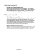
Problem You’ve configured more than one Ethernet device and some are communicating, but others aren’t. Solution It is easy to trouble shoot when you have some devices communicating (at least one). The quickest way to resolve the problem is first examine the lights on the PLC and Ethernet module for a device that is working. Compare this with one that isn’t working and then read the section on the prior page.
Trouble shooting network problems with older HydReclaim units Problem You’ve configured more serial devices and are having problems establishing communications. Solution Step 1: Disconnect the cable from all of the blenders except for the first one. Check communications. Be sure to read Chapter 4 before continuing. Step 2: If you still don’t have communications then ring out the cables.
You should see a response on the screen from the blender that looks something like: 01T00BTest String 6C If this works than communications is working. Try starting the blender and then perform the same test. If when the blender is running this test fails then the problem is noise from within the blender (consult service). If this test fails and you see scrolling junk on the screen then the problem is that you have noise on the com cable.
Trouble shooting network problems with ACS Mitsubishi blenders or Maguire WSB blenders Problem You’ve configured more than one Ethernet device and none of them are communicating. Pictures shown may differ with Maguire Digi One SP module, but the descriptions of LEDs and DIP switches are the same Solution It is easy to trouble shoot when you have some devices communicating (at least one), but with none communicating you’re going to have to start from the beginning.
Step 4: If all of the previous steps have been satisfied then examine the “LINK” light on the Ethernet module. It should not be red. If it is then first make sure that the Ethernet cable is hooked up at both ends. Remember that you must use straight through standard CAT5 cables when going between the blender and a hub or switch. If you are trying to go directly from the blender to a PC without using a hub or switch I’d then you need to use a Crossed Ethernet cable.
properties (see “Chapter1 Networking instructions for the ACS Mitsubishi Batch Blender” for step-by-step). Problem You’ve configured more than one Ethernet device and some are communicating, but others aren’t. Solution It is easy to trouble shoot when you have some devices communicating (at least one). The quickest way to resolve the problem is first examine the lights on the PLC and Ethernet module for a device that is working.
- Notes - Page Number 123
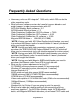
Other service problems or questions can be answered by contacting the ACS Service Department.
Service Notes Page Number 125
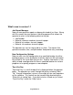
Parts Department Call [262] 641-8600 Parts shipped from the New Berlin, WI facility available for Next Day Air shipment only up to 3 pm CST. The ACS Parts Department at ACS, Inc. is ready to provide the parts to keep your systems up and running. Application Engineering replacement parts ensure operation at design specifications. Please have the model and serial number of your equipment when you call. Consult the Customer Parts List included in your information packet for replacement part numbers.