Operation and Installation Manual 2016-C Series Portable Hot Oil Temperature Control Units Important! Read Carefully Before Attempting to Install or Operate Equipment Part No. 682.94404.00 Revision 1 Bulletin No. SC1-645.
Write down your unit serial number(s) ________________ ________________ here for future reference ________________ ________________ ________________ ________________ ________________ ________________ Sterling is committed to a continuing program of product improvement. Specifications, appearance, and dimensions described in this manual are subject to change without notice. © Copyright Sterling, Inc. 2012 All rights reserved. Effective 4/27/2012 Part No. 682.94404.00 Revision 1 Bulletin No.
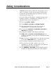
Safety Considerations STERLING 2016-C Series portable hot oil temperature control units are designed to provide safe and reliable operation when installed and operated within design specifications, following national and local safety codes. To avoid possible personnel injury or equipment damage when installing, operating, or maintaining this equipment, use good judgment and follow these safe practices: Follow all SAFETY CODES. Wear SAFETY GLASSES and WORK GLOVES.
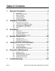
Table of Contents 1 General Information ................................................. 6 1-1 1-2 1-3 1-4 1-5 1-6 2 Shipping Information ............................................ 15 2-1 2-2 2-3 2-4 2-5 3 Page 4 The Microprocessor Controller ...................................................... 31 Controller Display .......................................................................... 31 Using Controller Keys ...................................................................
Charts and Figures Figure 1 2016-C Series Hot Oil Portable Temperature Control Unit and Specifications 14 Figure 2 2016-C Unit Piping Setup ................................................................................ 21 Figure 3 Typical E5CK Microprocessor Controller ........................................................ 31 Figure 4 Control Panel Switches ................................................................................... 33 Figure 5 18-24 GPM Pump Contrustion 075-00370-02 ............
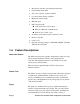
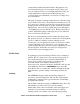
1 1-1 General Information Introduction Your STERLING 2016-C Series hot oil temperature control unit circulates thermal transfer-type oil through your process and to precisely, automatically, and reliably maintain it at a temperature you can select. The operating range of your temperature control unit is from 100°F to 400°F (38°C to 205°C). The unit is best suited for use with TrueTherm™ Heat Transfer Fluid.
1-3 Models Covered This manual lists installation, operation, and maintenance instructions for the 2016-C Series hot oil portable temperature control unit. Model numbers are listed on the serial tag. A model number followed by -Q indicates a specially constructed unit, and not all information in this manual may apply. Make sure that you know the model number, serial number, and operating voltage of your unit if you contact STERLING, Inc.
Hour meter; measures total pump run time hours General fault visual alarm Auto-vent sequence; deducts available Low level alarm; deducts available High level indicator light Manual bypass DIN controller with: 4-20 mA current control output RS-232 or RS-485 communications Remote sensor; 10 ft.
commercially available heat transfer fluids. The pump has only two internal moving parts, and a specially designed seal to give years of trouble free service, even at high temperatures. The only routine maintenance required is the monthly greasing and occasional head space adjustment; see Section 6-5 on Page 38 for more information. The pump is capable of running in either direction. Thus, the pump reverse feature can be used to draw fluids back from the process.
The controller automatically regulates cooling by opening and closing the cooling solenoid. This allows the proper amount of cooling water to pass through the tubes of the heat exchanger and out the drain. A water supply of 75 psi (517.1 kPa/5.2 bars) maximum is required for connection to the heat exchanger. Connection Lines Connections for TO PROCESS and FROM PROCESS lines are ½” NPT (12.5 mm). Water connections for COOLING WATER SUPPLY and COOLING WATER DRAIN are ½” NPT (12.5 mm). (see Section 3.
low fluid pressure low fluid level high fluid level (optional) Push the ALARM SILENCE button to silence the alarm. See Section 5 on page 31 for more information on control functions. Electrical Panel and System Components The pump motor and immersion heater operate on three-phase, 50/60 cycle, nominal voltage with the control circuit at 115 V single phase. The control circuit voltage is provided by a single phase machine tool transformer with primary fuse protection and a grounded secondary.
Air Purge Upon initial start-up and mold/process change-out, you’ll need to purge all air and water from the system. The 2016-C unit has appropriate valving to ensure complete purging; procedures are covered in Section 4 on Page 25. ! WARNING Failure to purge the system of air before heating may result in serious injury or critical system and equipment damage. Make sure you properly purge the system of air before starting the heater cycle.
Reservoir Tank A reservoir tank with sight gauge is standard; usable capacity is one (2) gallon (7.6 liters). The tank permits thermal expansion of the heat transfer fluid, and provides make-up fluid. ! WARNING The reservoir tank may cause serious injury if it ruptures from not being properly vented. Make sure that the reservoir tank is always properly vented to prevent tank rupture. The reservoir tank drain is extended beyond the base of the unit for ease of draining.
Figure 1 2016-C Series Hot Oil Portable Temperature Control Unit 2016-C Series Temperature Control Unit Specifications Model Pump Number Heater Power Pressure Flow 460 / 230 6 kW hp kW PSI Bar gpm lpm 2016-C Std. 0.75 0.56 50 3.45 6 22.8 Page 14 H in. 28 Dimensions W D cm in. cm in. cm 71 13 33 31 79 Shipping Weight lbs.
2 2-1 Shipping Information Unpacking and Inspection You should inspect your STERLING 2016-C Series hot oil portable temperature control unit for possible shipping damage. If the container and packing materials are in re-usable condition, save them for reshipment if necessary. Thoroughly check the equipment for any damage that might have occurred in transit, such as broken or loose wiring and components, loose hardware and mounting screws, etc.
2-3 If the Shipment is Not Complete Check the packing list. The apparent shortage may be intentional. Back-ordered items are noted on the packing list. You should have: 2016-C Series hot oil portable temperature control unit Bill of lading Packing list Operating and Installation packet Electrical schematic and panel layout drawings Component instruction manuals Re-inspect the container and packing material to see if you missed any smaller items during unpacking.
3 3-1 Installation Work Rules The installation, operation and maintenance of this equipment must be conducted in accordance with all applicable work and safety codes for the installation location. This may include, but is not limited to OSHA, NEC, CSA, and any other local, national and international regulations. 3-2 Read and follow these instructions when installing, operating and maintaining this equipment. If the instructions become damaged or unreadable, obtain additional copies from STERLING.
Make sure that the unit location is not in a confined space to ensure proper air circulation. Vapors can escape from areas such as the reservoir tank during high temperature operation. ! CAUTION Harmful vapors may be generated from thermal fluid during high temperature operation. Prolonged or repeated exposure of these hot-generated vapors may result in eye and respiratory tract irritation. Avoid contact or inhaling harmful amounts of material.
The following table lists TCO/TCU pipe sizes. Size diameter Connection inches NPT mm (approx.) To Process 0.5” NPT 12.5 mm From Process 0.5” NPT 12.5 mm Cooling Water Supply 0.5” NPT 12.5 mm Cooling Water Drain 0.5” NPT 12.5 mm Oil Drain 0.5” NPT 12.5 mm Fill Port 0.5” NPT 12.5 mm Customer is responsible for converting to metric. Notes: Always use a backup wrench to support 2016-C unit piping when making connections. Make sure all external piping is supported independently of the 2016-C unit.
Connecting Process Piping ! CAUTION Hoses, valves and other components in your process must be able to withstand 2016-C unit maximum temperatures and pressures. Maximum temperatures and pressures are listed on the unit nameplate. Carefully inspect all components before installation. If in doubt about component suitability, obtain factory components. Fix all leaks! Fluid can be a potential fire and slip hazard.
! CAUTION The reservoir tank must be vented to prevent pressurization. A pressurized reservoir could rupture, allowing hot fluid to escape and become a potential fire and slip hazard. Note: Heat transfer fluids expand when heated. Expansion rates vary, depending on fluid types and temperatures. For more information on expansion rates, refer to specification information for the heat transfer fluid you select. Generally, most heat transfer fluids expand at the rate of 2.
! CAUTION If you are routing the drain line to an open drain, make sure that the line is directed away from personnel to avoid scalding. Carefully select connecting lines and connectors between the 2016-C unit and the process to best meet the needs and requirements of your application. Make sure lines and connectors have a service rating of at least 100 psig (689.5 kPa/6.9 bars), and a temperature ratingat least equal to the maximum operating temperature of your 2016-C unit.
When running conduit whips to the 2016-C unit, make sure that whips are routed away from hot piping. Check the unit nameplate for correct voltage and amperage before making electrical connections! ! DANGER Improper electrical connections can damage the unit and cause serious operator injury or death! Make sure that all electrical connections are made by a qualified electrician, and that all connections are tight. Make all electrical supply connections at the front of the unit.
- Notes - Page 24 2016-C Series Hot Oil Portable Temperature Control Units
4 Startup Preparations 4-1 Starting the Unit Unit Start-up (With Autovent Solenoid) The highly engineered controls and controller make this unit almost self operating. Before you can begin heating, it will be necessary to perform the following start up procedures. This will ensure that all air is vented from the system to prevent fluid degradation and damage to the heater. 1. Add fluid to the reservoir tank until the level is near the top of the sight glass. 2.
7. If any water is present in the system, it must be boiled off before continuing operation. Select a setpoint of 215ºF (102ºC) and observe the reservoir tank vent for any signs of escaping steam. Continue to run at 215ºF until no more steam appears and pressure has stabilized. 8. When fluid level has stabilized and air and water is purged from the system, allow the vent timer to run out.
8. If any water is present in the system, it must be boiled off before continuing operation. Select a setpoint of 215ºF (102ºC) and observe the reservoir tank vent for any signs of escaping steam. Continue to run at 215ºF (102ºC) until no more steam appears and pressure has stabilized. 9. When fluid level has stabilized and air and water is purged from the system, close the Vent Valve. Do not open the Vent Valve above 250°F.
4-3 Returning Fluid to the Tank Returning Fluid to Tank (With Autovent Solenoid) If the unit is to be moved from one process to another (i.e. mold changes, etc.), the following steps must be taken to drain the mold and process lines. Note that this is just the opposite of unit start up/air purge: 1. Cool fluid to 100 degrees °F maximum. 2. Turn the Pump Rev|Off|Fwd switch to Off. 3. Turn the Pump Rev|Off|Fwd switch to Rev.
Returning Fluid To Tank (With Manual Vent Valve) If the unit is to be moved from one process to another (i.e. mold changes, etc.), the following steps must be taken to drain the mold and process lines. Note that this is just the opposite of unit start up/air purge: 1. Cool fluid to 100 degrees °F maximum. 2. Open the Vent Valve to allow in fresh air into the pipes. 3. Turn the Pump Rev|Off|Fwd switch to Off. 4. Turn the Pump Rev|Off|Fwd switch to Rev.
- Notes - Page 30 2016-C Series Hot Oil Portable Temperature Control Units
5 5-1 Using Controls and Indicators The Microprocessor Controller The controller is an easy-to-operate microprocessor-based PID control device. When the process reaches the set point, the controller cycles the cooling valve or the immersion heater to maintain the proper To Process temperature. The controller has been fully factory tested. Set the desired process temperature set point and the control does the rest. Built-in range of operation on the controller is 0°F to 400°F (-18ºC to 205ºC).
5-3 Using Controller Keys See Figure 3 Page Key From any display – press to return to the HOME display. Scroll Key Press to select a new parameter. If held down it will continuously scroll through the parameters. Important! Do not change any of the control settings without consulting the STERLING Service Department. The STERLING, Inc.
Figure 4 Control Panel Switches Pump Rev|Off|Fwd Turn the Pump Rev|Off|Fwd switch to Fwd to start the pump in the normal forward direction. Turn the Pump Rev|Off|Fwd switch to Off to stop the pump and de-energize the controller. ! CAUTION Always turn to Pump Off and allow the pump to come to a complete stop before turning to Pump Reverse. Failure to let the pump stop before reversing may damage the pump and drive. Turn the Pump Rev|Off|Fwd switch to Rev to start the pump in the reverse direction.
returns to the Center Default position when in AUTO mode. The switch stays in the Maintained position in Manual Cooling mode. ! CAUTION Always let the pump run for at least one (1) minute before switching to AUTO mode. Never switch to AUTO mode when filling or venting the unit, except as described in the Unit Startup chapter. Improper switching can seriously damage the heater, as it could become energized with air in the system. Alarm Silence Press the ALARM SILENCE on the console.
6 Preventive Maintenance ! WARNING Make sure that your maintenance technicians comply with lock-out/tag-out procedures during any servicing or maintenance of this unit and related equipment, per OSHA article ART 1910.147. Before you begin servicing this unit, disconnect all power to the unit, let the unit cool down completely, and turn off the water.
Making Quarterly Checks Check the heat transfer fluid for deterioration. If the fluid is noticeably darker, or it seems significantly thicker, drain the system and replace the fluid with fresh, new recommended heat transfer fluid. Do a routine check of the fluid every 1,000 hours of operation or every three (3) months, whichever comes first. Contact STERLING, Inc. Service for information on fluid testing.
Servicing the Unit Monthly or Every 500 Hours Lubricate the pump at the grease fittings with Dow-Corning #44 or a high-quality lithium grease rated at 400ºF (204ºC) or higher that is compatible with Dow-Corning #44. Do not over-lubricate. Adjust the pump drive belt tension. Make sure that the motor pulley is properly aligned with the pump pulley; use a straightedge to check. Tighten motor mounting bolts after realignment. Inspect the screen in the Y strainer for accumulations of debris.
If the unit stands idle for a long time before being installed in your factory, gaskets can dry out and possibly leak when you start the unit. In most cases, these gaskets soon swell and form a tight seal. If not, you may need to tighten the bolts to stop the leak. Similarly, rough handling in shipping may sometimes cause minor leaks upon startup; you may need to re-tighten bolts or fittings to stop the leak. You should expect to periodically replace the pump seal.
Figure 5 18-24 GPM Pump Construction 075-00370-02 COT-C Series Hot Oil Portable Temperature Control Units Page 39
Disassembling the Pump 1. Mark head and casing before disassembly to insure proper reassembly. The idler pin, which is offset in the pump head, must be positioned toward and equal distance between port connections to allow for proper flow of liquid through pump. Remove head from pump. Do not allow idler to fall from idler pin. To prevent this tilt top of head back when removing. Avoid damaging head gasket. 2. Remove idler and bushing assembly. 3.
removed from the pump. Note the mechanical seal may stick to the shaft causing initial resistance when the shaft is removed. 10. Remove the mechanical seal parts from the bracket. 11. Clean all parts thoroughly and examine for wear and damage. Check lip seals, ball bearing, bushings and idler pin and replace if necessary. Check all other parts for nicks, burrs, excessive wear and replace if necessary. Wash bearings in clean solvent. Blow out bearings with compressed air.
3. Coat idler pin with non-detergent SAE 30 weight oil and place idler and bushing on idler pin in head. If replacing with carbon graphite bushing, Refer to Installation of Carbon Graphite Bushings, page 50. 4. Using a .010 to .015 inch head gasket, install head and idler assembly on pump. Pump head and casing were marked before disassembly to insure proper reassembly.
8. Pack ball bearing with Dow Corning #44 high temperature silicon grease and install in the thrust bearing housing. Place bearing spacer collars inside the lip seals. Thread the end cap into the bearing housing and tighten with a spanner wrench. Tighten the radial set screws that lock the end cap in place. 9. Using the snap ring pliers, install the snap ring onto the shaft. 10 Thread the thrust bearing assembly into the bracket. Turn until hand tight. This forces the rotor against the head. 11.
Thrust Bearing Adjustment 1. Loosen axial setscrews in face of end cap on the thrust bearing assembly. If rotor shaft cannot be turned by hand, back off the thrust bearing assembly until there is a noticeable drag of the shaft. Note mechanical seal will provide some drag and this is a normal condition. The thrust bearing assembly must be turned in until it can just be turned over by hand. This ensures the rotor is against the head and a zero end clearance condition exists. 2.
Installation of Carbon Graphite Bushings When installing carbon graphite bushings, extreme care must be taken to prevent breaking. Carbon graphite is a brittle material and easily cracked. If cracked, the bushing will quickly disintegrate. Using a lubricant and adding a chamfer on the bushing and the mating part will help in installation. The additional precautions listed below must be followed for proper installation: 1. A press must be used for installation. 2. Be certain bushing is started straight. 3.
Preventative Pump Maintenance You can extend the life of your pump and reduce the cost per gallon pumped if you perform a few preventive maintenance procedures. Lubricating the Pump Using #2 ball bearing grease and a hand-operated grease gun gently lubricate all grease fittings after every 500 hours of operation or after 60 days, whichever comes first. If pump service occurs in severe conditions, lubricate more frequently. Use an appropriate type of grease for hot or cold applications.
COT-C Series Hot Oil Portable Temperature Control Units Page 47
Figure 8 Customer Recommended Spare Parts Immersion Heaters Part number 722-00138-01 722-00138-02 722-00138-03 722-00138-04 722-00138-05 722-00138-06 Description HTR, IMM, 6 KW, 208 V, 3”, 6 ELE HTR, IMM, 6 KW, 240 V, 3”, 6 ELE HTR, IMM, 6 KW, 380 V, 3”, 6 ELE HTR, IMM, 6 KW, 415 V, 3”, 6 ELE HTR, IMM, 6 KW, 480 V, 3”, 6 ELE HTR, IMM, 6 KW, 600 V, 3”, 6 ELE Note: 6 kW heaters are modified 12 kW heaters; jumpers are remove from one leg.
Figure 8 Customer Recommended Spare Parts Cont’d. Pressure Gauge Part number 037-00158-00 Description GAUGE, PRESSURE, 0 — 100 PSI Heat Exchanger Ass’y. part no. 106-00024-00 Description 1.5 SQ. FT. 2016-C 400°F Casters Part number 042-00016-00 042-00017-00 Description CASTER, SWIVEL, 3” CASTER, STATIONARY, 3” Sight Glass Assembly Part number 037-00047-00 Description GLASS, SIGHT, 27” Note: Please give model and serial numbers when ordering parts. Prices are subject to change without notice.
Figure 8 Customer Recommended Spare Parts Cont’d.
Figure 8 Customer Recommended Spare Parts Cont’d. Solenoid Valves Part number 732-00007-03 732-00012-02 Description ¼” VENT VALVE, 115 V COIL (0-125 PSI, 300°F) ½” VENT VALVE, 115 V COIL (0-125 PSI, 300°F) Sensing Probe Equipment Part number 701-00036-00 692.07369.
7 Troubleshooting Condition Possible cause Undersized connectors/lines. Long connecting lines between unit and mold. Serpentine flow through mold. Blocked line in mold. Temperature fluctuations/rapid cycling from hot to cold. Quick disconnect fitting with check valve. Carbon build-up in unit piping or fittings. Faulty TCU. Reversed probes. Loss of fluid in process. Vent valve open. Unit does not heat properly/can not achieve set point.
Troubleshooting Cont’d. Condition Possible cause Controller heater output open. Unit does not heat. (cont’d.) Unit overheats/unable to cool. Clogged Y strainer. Water supply to unit is turned OFF. Water drain is plugged or excessive back pressure in drain line. Heat exchanger tubes plugged by lime deposits. Faulty solenoid valve. Leaks in connecting lines. Air in circulating lines. Low fluid. Defective Ful-Flo valve. Rapid drop in pressure/no pressure. Water in fluid. Vent solenoid open.
DIAGRAMS FLOW & ELEMENTARY ELECTRICAL Please refer to Electrical Drawings Provided in Packet with Unit Page 54 2016-C Series Hot Oil Portable Temperature Control Units
Service Notes COT-C Series Hot Oil Portable Temperature Control Units Page 55
Service Notes Page 56 2016-C Series Hot Oil Portable Temperature Control Units
Service Notes COT-C Series Hot Oil Portable Temperature Control Units Page 57
Service Notes Page 58 2016-C Series Hot Oil Portable Temperature Control Units
Service Notes COT-C Series Hot Oil Portable Temperature Control Units Page 59
Index Adjusting End Clearance, 46 Air Purge, 12 Alarm Silence, 34 Alarm Silence, 12, 11 Available Options, 7 Charts and Figures, 5 Connecting Cooling Water Piping, 20 Connecting Piping, 18 Connecting Process Piping, 20 Connecting Vent Piping, 20 Connection Lines, 10 Control Unit Specifications, 14 Controller display, 31 Corrective Maintenance, 37 Pumps and Seals, 37 Down key, 32 Draing Unit for Storage, 37 Electrical Connections, 22 Electrical Panel and System Components, 11 Electrical System Controls, 10 F
Parts Department Call toll-free 7am–6pm CST [800] 423-3183 or call [262] 641-8610, Fax [262] 641-8653 The ACS customer service group will provide your company with genuine OEM quality parts manufactured to engineering specifications, which will maximize your equipment’s performance and efficiency. To assist in expediting your phone or fax order, please have the model and serial number of your unit when you contact us. A customer replacement parts list is including in this manual for your convenience.