
Instruction Manual

Mark 968 Sanitary GaS reGulator
-9-
2" n
2
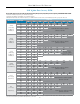
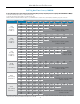
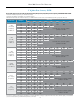
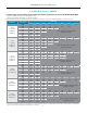
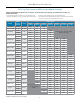
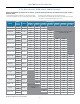
Flow capacities: scFH (sHaded), nM
3
/H (unsHaded)
Range
Outlet
Pressure
Set Point
Accuracy
Inlet Pressure
2.0 psi
(0,14 bar)
3.0 psi
(0,21 bar)
5.0 psi
(0,34 bar)
10.0 psi
(0,69 bar)
15.0 psi
(1,03 bar)
20.0 psi
(1,38 bar)
25.0 psi
(1,72 bar)
2.0-5.0" WC 3.0" WC 0.75" WC 5392 5761 6666
4,98-12,5 mbar 7,47 mbar 1,87 mbar 153 163 189
4.0-8.0" WC
5.0" WC
1" WC
5195 6147 7498 9554
7.0" WC 5541 6385 7202 7760
9,96-19,93 mbar
12,45 mbar
2,49 mbar
147 174 212 271
17,44 mbar 157 181 204 220
8.0-28.0" WC
10.0" WC
1.5" WC
6223 5885 7358 8578 9408 8486
25.0" WC 4770 5191 4841 5398 7640 8022
19,93-69,75 mbar
24,91 mbar
3,74 mbar
176 167 208 243 266 240
62,27 mbar 135 147 137 153 216 227
10.0-17.0" WC
12.0" WC
2" WC
5091 6649 7965 11519 11365 12042
15.0" WC 4775 5778 7901 10864 11456 11942
24,91-42,35 mbar
28,89 mbar
4,98 mbar
144 188 226 326 322 341
37,36 mbar 135 164 224 308 324 338
14.0-28.0" WC
15.0" WC
2.5" WC
4523 6374 9179 12013 13409 14904 14578
25.0" WC 3470 4986 7416 10063 11991 12898 14376
34,87-69,75 mbar
37,36 mbar
6,23 mbar
128 180 260 340 380 422 413
62,27 mbar 98 141 210 285 340 365 407
0.75-1 psi
0.75 psi
0.25 psi
5382 8059 10698 12859 15370 16976 18931
1 psi 5153 6984 10556 12841 15436 16948 18918
51,71-68,95 mbar
51,71 mbar
12,93 bar
152 228 303 364 435 481 536
68,75 mbar 146 198 299 364 437 480 536
1-2 psi
1.5 psi
0.3 psi
4835 9706 12810 15508 17238 19286
2.0 psi 3895 8431 12534 15293 17056 19118
68,95-137,0 mbar
0,10 bar
20,69 mbar
137 275 363 439 488 546
0,14 bar 110 239 355 433 483 541
1.5-3 psi
2.0 psi
0.4 psi
4365 8927 12599 15412 17185 19258
3.0 psi 6731 12138 15140 17030 19169
0.10-0,21 bar
0,14 bar
27,50 mbar
124 253 357 436 487 545
0,21 bar 191 344 429 482 543
3-5 psi
3.5 psi
0.5 psi
3897 11979 15109 17072 19258
5.0 psi 10710 14214 16314 18543
0,21-0,34 bar
0,24 bar
34,38 mbar
110 339 428 483 545
0,34 bar 303 402 462 525
Nitrogen at 0.97 s.g. in scfh and Nm
3
/h.
Operation in shaded areas not recommended.
Flow in this area is outside the operating
parameters of the valve
Flow in this area is outside
the operating parameters of
the valve
To find the maximum flow rate that this valve can control to, you need to know P1 (inlet pressure), P2 (outlet pressure set point), and maxi-
mum flow in SCFH.
1. Select the Range row that encompasses your outlet Set Pressure (P2). 3. Select the column that best represents your Inlet Pressure (P1).
2. Select the sub-row that is closest to your actual outlet Set Pressure (P2) 4. The maximum flow rate that the valve can regulate is the number represented at the
intersection of the sub row and the Inlet Pressure column.