
Instruction Manual

-8-
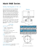
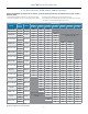
Mark 968 Sanitary GaS reGulator
1-1/2" n
2
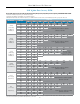
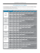
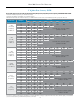
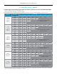
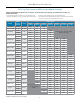
Flow capacities: scFH (sHaded), nM
3
/H (unsHaded)
Range
Outlet
Pressure
Set Point
Accuracy
Inlet Pressure
2.0 psi
(0,14 bar)
3.0 psi
(0,21 bar)
5.0 psi
(0,34 bar)
10.0 psi
(0,69 bar)
15.0 psi
(1,03 bar)
20.0 psi
(1,38 bar)
25.0 psi
(1,72 bar)
2.0-5.0" WC 3.0" WC 0.75" WC 4853 5185 5999
4,98-12,5 mbar 7,47 mbar 1,87 mbar 137 147 170
4.0-8.0" WC
5.0" WC
1" WC
4675 5532 6748 8599
7.0" WC 4987 5747 6482 6984
9,96-19,93 mbar
12,45 mbar
2,49 mbar
132 157 191 243
17,44 mbar 141 163 184 198
8.0-28.0" WC
10.0" WC
1.5" WC
5601 5297 6622 7720 8468 7638
25.0" WC 4293 4672 4357 4858 6876 7220
19,93-69,75 mbar
24,91 mbar
3,74 mbar
159 150 188 219 240 216
62,27 mbar 122 132 123 138 195 204
10.0-17.0" WC
12.0" WC
2" WC
4582 5984 7169 10367 10228 10838
15.0" WC 4297 5200 7111 9778 10310 10748
24,91-42,35 mbar
28,89 mbar
4,98 mbar
130 169 203 294 290 307
37,36 mbar 122 147 201 277 292 304
14.0-28.0" WC
15.0" WC
2.5" WC
4070 5737 8261 10811 12068 13414 13120
25.0" WC 3123 4487 6675 9057 10792 11608 12938
34,87-69,75 mbar
37,36 mbar
6,23 mbar
115 162 234 306 342 380 372
62,27 mbar 88 127 189 256 306 329 366
0.75-1 psi
0.75 psi
0.25 psi
4843 7253 9628 11573 13833 15278 17038
1 psi 4638 6286 9501 11557 13892 15253 17026
51,71-68,95 mbar
51,71 mbar
12,93 bar
137 205 273 328 392 433 482
68,75 mbar 131 178 269 327 393 432 482
1-2 psi
1.5 psi
0.3 psi
4352 8736 11529 13957 15514 17358
2.0 psi 3505 7588 11281 13764 15351 17206
68,95-137,0 mbar
0,10 bar
20,69 mbar
123 247 326 395 439 492
0,14 bar 99 215 319 390 435 487
1.5-3 psi
2.0 psi
0.4 psi
3929 8034 11339 13871 15466 17332
3.0 psi 6057 10924 13626 15327 17252
0.10-0,21 bar
0,14 bar
27,50 mbar
111 228 321 393 438 491
0,21 bar 172 309 386 434 489
3-5 psi
3.5 psi
0.5 psi
3507 10781 13598 15365 17332
5.0 psi 9639 12792 14682 16688
0,21-0,34 bar
0,24 bar
34,38 mbar
99 305 385 435 491
0,34 bar 273 362 416 473
Nitrogen at 0.97 s.g. in scfh and Nm
3
/h.
Operation in shaded areas not recommended.
Flow in this area is outside
the operating parameters of
the valve
Flow in this area is outside the operating
parameters of the valve
To find the maximum flow rate that this valve can control to, you need to know P1 (inlet pressure), P2 (outlet pressure set point), and
maximum flow in SCFH.
1. Select the Range row that encompasses your outlet Set Pressure (P2). 3. Select the column that best represents your Inlet Pressure (P1).
2. Select the sub-row that is closest to your actual outlet Set Pressure (P2) 4. The maximum flow rate that the valve can regulate is the number represented at the
intersection of the sub row and the Inlet Pressure column.