
Instruction Manual
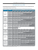
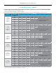
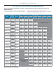

Set Pressure Inlet (psi)
Orifice Size
1/8" 3/16" 1/4" 5/16" 3/8" 7/16" 1/2" 9/16"
2" H20
(1-2.5" H20)
1" H20 Droop
2" H20 Boost*
5 226 420 483 630 536 998 1172 1313
10 328 618 702 893 779 1206 1450
20 493 872 1055 1376 803
40 786 1224 1681 2010
60 1073 1447 1872
80 1360 1455 1898
100 1648 1763
150 2146 2256
3" H20
(2-5" H20)
1" H20 Droop
2" H20 Boost*
5 268 419 565 629 689 996 1307 1342
10 356 618 870 892 910 1205 1503
20 469 872 1266 1376 656
40 730 1224 1707 2010
60 963 1447 1926
80 1255 1455 1627
100 1534 1763
150 1981 2256
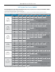
7" H20
(4-10" H20)
1" H20 Droop
2" H20 Boost*
5 283 378 477 524 565 793 1024 848
10 380 585 791 722 653 1003 1345
20 488 871 1247 1684 2110 2177
35 673 1444 2188 2358 2525 3155
75 1221 2278 3317
90 1399 2623
100 1534 2836
150 1981 3687
28" H20
(5-30" H20)
5-1/2" H20 Droop
5 318 478 636 760 883 991 1095 1130
10 388 613 831 1128 1424 1584 1741
30 373 1074 1756 2192 2608 2834
45 718 1596 2393 2892
60 929 2121 3302 3294
75 1139 2517
100 1449 3219
150 1871 4182
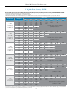
1.25 psi
(0.5 - 1.75 psi)
0.2 psi Droop
5 198 299 482 434 578 511 723 1012
10 267 378 593 608 890 756 1038 964
30 328 552 969 924 1193 1342
45 479 758 1197 1157 1396
60 624 998 1497 1398 1622
75 689 1229 1858
100 920 1609 2376
150 1211 2091 3081
3 psi
(1 - 3.5 psi)
0.3 psi Droop
5 159 238 318 346 371 408 442 742
10 237 355 475 571 672 710 752 831
30 266 550 825 921 1011 1337
45 479 758 1097 1157 1157
60 619 998 1376 1398 1410
75 689 1229 1708
100 852 1609 2387
150 1100 2091 3081
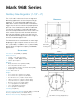
Mark 968 Sanitary GaS reGulator
1" n
2
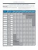
Max Flow capacity: scFH
Flow in this area is outside the operating
parameters of the valve
Flow in this area is outside the operating
parameters of the valve
Flow in this area is outside the operating
parameters of the valve
Flow in this area is outside the operating
parameters of the valve
Flow in this area is outside the operating
parameters of the valve
Flow in this area is outside the operating
parameters of the valve
* Boost refers to a small rise in outlet pressure set point that can occur, and is characteristic of, this type of regulator when flow nears the valve's maximum capacity. To understand this
phenomenon and to determine your maximum flow requirements, see API 2000
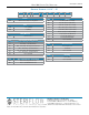
To select the orifice size for your valve you need to know P1 (inlet pressure). P2 (outlet pressure set point), and maximum flow in SCFH.
1. Select the row that best represents your outlet Set Pressure (P2)
2. Select the sub-row that is representative of your Inlet Pressure (P1)
3. Find the Flow rate in that sub-row that encompasses your maximum flow. Look at the orifice column heading to determine your specific orifice size.
-4-