
Instruction Manual
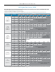

Set Pressure Inlet (psi)
Orifice Size
1/8" 3/16" 1/4" 5/16" 3/8" 7/16" 1/2" 9/16"
2" H20
(1-2.5" H20)
1" H20 Droop
2" H20 Boost*
5 201 374 430 261 477 888 1043 1169
10 213 402 456 580 506 784 943
20 222 392 475 619 361
40 299 465 639 764
60 665 897 1161
80 816 873 1139
100 598 640
150 770 825
3" H20
(2-5" H20)
1" H20 Droop
2" H20 Boost*
5 239 373 503 560 613 886 1163 1195
10 231 402 566 580 591 783 977
20 211 392 570 619 295
40 277 465 649 764
60 597 897 1194
80 753 873 976
100 675 776
150 880 825
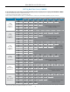
7" H20
(4-10" H20)
1" H20 Droop
2" H20 Boost*
5 220 295 372 409 441 619 799 661
10 277 427 578 527 476 732 982
20 258 462 661 893 1118 1154
35 276 592 897 967 1035 1294
75 525 980 1426
90 727 1364
100 813 1503
150 1040 1926
28" H20
(5-30" H20)
5-1/2" H20 Droop
5 302 454 604 722 839 941 1040 1074
10 337 533 723 981 1239 1378 1514
30 283 816 1335 1666 1982 2154
45 617 1373 2058 2487
60 817 1866 2906 2899
75 820 1812
100 840 1867
150 1089 2421
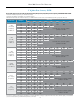
1.25 psi
(0.5 - 1.75 psi)
0.2 psi Droop
5 180 272 439 395 526 465 658 921
10 235 333 522 535 783 665 913 848
30 279 469 824 785 1014 1141
45 354 561 886 856 1033
60 418 669 1003 937 1087
75 427 762 1152
100 543 949 1402
150 715 1266 1816
3 psi
(1 - 3 .5 psi)
0.3 psi Droop
5 145 217 289 315 338 371 402 675
10 209 312 418 502 592 625 661 731
30 226 468 701 783 859 1136
45 354 561 812 856 856
60 415 669 922 937 945
75 427 762 1059
100 503 949 1408
150 660 1266 1816
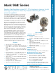
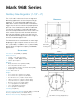
Mark 968 Sanitary GaS reGulator
3/4" n
2
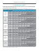
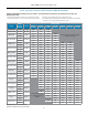
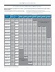
Max Flow capacity: scFH
Flow in this area is outside the operating
parameters of the valve
Flow in this area is outside the operating
parameters of the valve
Flow in this area is outside the operating
parameters of the valve
Flow in this area is outside the operating
parameters of the valve
Flow in this area is outside the operating
parameters of the valve
Flow in this area is
outside the operating
parameters of the valve
* Boost refers to a small rise in outlet pressure set point that can occur, and is characteristic of, this type of regulator when flow nears the valve's maximum capacity. To understand this
phenomenon and to determine your maximum flow requirements, see API 2000
To select the orifice size for your valve you need to know P1 (inlet pressure). P2 (outlet pressure set point), and maximum flow in SCFH.
1. Select the row that best represents your outlet Set Pressure (P2)
2. Select the sub-row that is representative of your Inlet Pressure (P1)
3. Find the Flow rate in that sub-row that encompasses your maximum flow. Look at the orifice column heading to determine your specific orifice size.
-2-