
Instruction Manual

Mark 901 SerieS Cavity-Filled Ball valveS
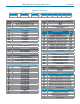
MaterIal specIFIcatIons
L1
Size,
NPS
Body Pressure
Rating
Valve Name Plate Pressure
Rating, PSI
Clamp End
1
Tube End
1
1/2" 1000 500 1000
3/4" 1000 500 1000
1" 1000 500 1000
1-1/2" 1000 500 1000
2" 1000 450 750
2-1/2" 800 400 50
3" 800 350 625
4" 800 300 600
4
13
17
Ød
ValVe naMe plate ratIng
1
Clamp end name plate pressure rating is based on Tri-Clover A13MHM
Tri-Clamp (hinged 2-segment clamp with wing nut)
2
Tube end name plate pressure rating is the lesser of the body rating or
the tube end rating calculated with ANSI B31.3 using Sy-20ksi
Y=0.4 and E=0.8
No. Part Material Qty
1 Body ASTM-A351-CF3M 1
2 Cap ASTM-A351-CF3M 2
3 Ball ASTM-A351-CF3M 1
4 Seat PTFE / TF 1641 2
5 Gasket PTFE / TF 1641 2
6 Stem ASTM A276 316 1
7 Thrust Washer PTFE / TF 1641 1
8 Stem Packing PTFE / TF 1641 1
9 Bolt AISI 304 4
10 Hex Nut AISI 304 4
11 Bolt Washer AISI 304 4
12 Bevel Washer AISI 304 2
13 Nut AISI 304 1
14 Nut AISI 304 1
15 Handle AISI 304 1
16 Handle Cover Vinyl 1
17 Lock Device AISI 304 1
18 Stop Pin AISI 304 1
Size
Oper.
Torque
in-lbs (Nm)
Cv (Kv)
Weight Lb (Kg)
Clamp End BWE
1/2" 80 (9,1) 9 (7,7) 1.6 (0,72) 1.54 (0,70)
3/4" 85 (9,6) 26 (22,4) 2.0 (0,90) 1.90 (0,86)
1" 100 (11,3) 61 (52,5) 2.7 (1,2) 2.6 (1,2)
1-1/2" 250 (28) 193 (166) 5.8 (2,6) 5.6 (2,6)
2" 350 (40) 432 (372) 8 (4) 8 (4)
2-1/2" 600 (68) 728 (626) 18 (8) 17 (8)
3" 860 (97) 1125 (968) 25 (11) 25 (11)
4" 990 (112) 1986 (1708) 46 (21) 46 (21)
technIcal specIFIcatIons
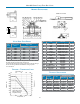
pressure – teMperature chart
1100
1000
900
800
700
400
0
0 100 200 300 400
Temperature, °F
Pressure, psi
-2-
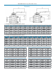
ØD2
L1
7
8
12 18
6
14 15
16
101131529
L
200
76
69
62
55
48
41
0
35
28
21
Pressure, bar
-18 38 93 149 204
Temperature, °C
Handle for 4" valve
G
B
A
DIN3337
ISO5211
1/2"-2"
2-1/2"-4"
Ød
ØD1
ØF
7
14
600
500
300
100
Graph shows body
center rating. Clamp
ttings or tube ends
may reduce rating