
User Manual
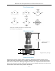

JSR SeRieS HigH PuRity Bio-PHaRma gaS PReSSuRe Reducing ValVe
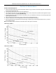
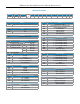
trim Flow (cv) selection Graphs
J perFormance 0.5 cv
0
10
20
30
40
50
0
10
20
30
40
50
60
70
80
90
100
P1 = 150 psig
P1 = 150 psig
P1 = 100 psig
P1 = 100 psig
Air Flow (SCFM)
Outlet Pressure - P2 (psig)
J perFormance 0.8 cv
0 10 20 30 40 50
Air Flow (SCFM)
60 70 80
0
10
20
30
40
50
60
70
80
90
100
P1 = 150 psig
P1 = 150 psig
P1 = 100 psig
P1 = 100 psig
Outlet Pressure - P2 (psig)
-4-
To select a valve with the proper Cv:
1. Please note maximum inlet pressure, and seat temperature limitations on page 2. Select a seat material appropriate for that temperature
and the gas owing through the valve.
2. Convert pressure and ow units to those shown in the graphs below.
3. The sloped lines are the ow curves associated with either a 150 psi or 100 psi inlet pressure (P1). Make sure the application inlet pres-
sure is between 100 and 150 psi. If not, contact the factory.
4. Select the graph that encompasses the minimum and maximum ows of your installation (horizontal axis), and with an appropriate outlet
regulated pressure (vertical axis).
5. Plot your desired set point on the graph you chose, at the ow rate you expect at that set point.
6. Pick the P1 inlet pressure curve in your graph that is closest to your valve installation inlet pressure.
7. Draw a curve with the same slope parallel to that curve through your plotted set point. That curve approximates the ow of your valve
under operating conditions.
Note: if your operating conditions and media are outside the bounds of either graph, consult factory.