
Installation Guide

9
• Once the cable is installed, but before it is covered with concrete or mortar. If the tests indicate that the cable is defective, the electrician is
responsible for xing the problem.
• Once the cable is fully installed, covered and the oor covering is dry. If the tests indicate that the cable is defective, the contractor is res-
ponsible for xing the problem (i.e. replacing the cable and redoing the installation).
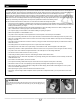
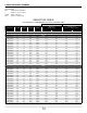
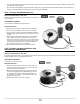
TEST 1: CONDUCTOR RESISTANCE TEST
WHAT’S THE PURPOSE OF THIS TEST?
This test ensures that the product is in good working order and has the
proper resistance.
INSTRUMENTS REQUIRED
An ohmmeter or multimeter is required for this test.
PERFORM THE TEST
1. Make sure your ohmmeter or multimeter has been calibrated.
2. If you are using a multimeter, select the “Ohm” or “Ω” setting.
3. If you are using a manual range selection multimeter, select the
smallest range of ohms that covers the nominal ohms of the mat
or cable.
4. Take a reading of the resistance between the two power leads
(120 V: black and yellow, 240 V: black and red). If there is a
wide variance in the ohms reading, that is, if the measured value
is 10 ohms or 10% higher than the nominal value printed on the
product’s label, it either means that the product is damaged or
the measuring instrument is not well calibrated.
5. Record the ohms measurement in your warranty booklet.
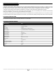
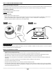
TEST 2: CONDUCTOR NON-CONTINUITY AND
GROUND TEST (GREEN WIRE)
WHAT’S THE PURPOSE OF THIS TEST?
The heating cable is protected by a ground braid, and an electrical insulator prevents any contact between the braid and the conductor. This test
indicates whether there is any continuity between them.
INSTRUMENTS REQUIRED
A multimeter is required for this test.
PERFORM THE TEST
1. Select the highest resistance setting on your multimeter and
proceed downward, or select “Ohm” or “Ω” if you are using an
automatic range selection multimeter.
2. Measure the resistance between the grounding wire and one
of the two power leads (BLACK or RED/YELLOW). If there is
no continuity between them, the multimeter will display “OL”
for “overload” or “I” for “innity”. If the test fails, the meter will
display a numbered result.
3. Record the test result in your warranty booklet.
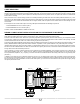
TEST 1
FIG. 5
BRAID OR
GREEN WIRE
TEST 2
FIG. 6
BRAID OR
GREEN WIRE