
Installation Guide

6
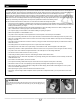
PLANNING AND DESIGN
CABLE SELECTION
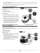
Before getting started, consider what the heating goal is for the room. Do you want to heat the entire room or simply keep your feet warm? The
answer to this question will determine the spacing between cable runs; a 3-space runs will heat a room without the need for a secondary source
of heating (baseboard or convector), while 4-space runs will keep feet warm but, for greater comfort, the system will need to be combined with
another source of heating.
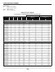
Next, measure the room’s square footage (surface to be heated) subtracting the areas that cannot be heated (cabinets, bathtubs, etc.). Then,
depending on the cable installation method used (membrane ou cable spacers), choose the right product. Refer to this guide’s Coding and model
numbers section. If the surface size falls between the size ranges offered, select the product for the smaller surface to avoid having too much
unused cable.
For example, the 32-ft
2
surface with 3-space runs using cable spacers falls between the following two products:
1. SCU1W0338S030 for a 29.5 ft
2
surface (120 V)
2. SCU1W0405S036 for a 35 ft
2
surface (120 V)
Therefore, model SCU1W0338S030 is suitable for this room.
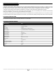
DESIGN A CABLE LAYOUT INSTALLATION PLAN FOR THE SURFACE TO BE HEATED
To facilitate the installation process, it’s essential to draw a plan of the heating cable layout. To this end, rst determine the thermostat location
which will be the starting point for the cable run and the sensor. Then, determine the thermostat sensor location.
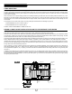
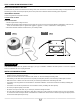
There are a few basic rules to follow. Because it is practically impossible to predict precisely where the cable will end, you must plan the location
of a buffer zone. A buffer zone is an area of the oor where heating is not essential, typically behind a toilet or beside a door opening. The area
could be heated with the excess cable or not, without causing any discomfort (see FIG. 1).
The heating cable SHOULD NEVER overlap another cable. Overlapping will generate a hot spot that could damage the cable and lead to over-
heating. NEVER install the heating cable under kitchen cabinets, a cupboard, counter, podium bathtubs or any other xed piece of furniture.
Install the thermostat sensor away from direct sunlight or a supplementary heating source. It must not cross over the heating cable. The thermo-
stat sensor must be installed between two cable runs, at least 24 inches (60 cm) from the wall, or centered in between walls. Make sure you have
enough cable to reach the thermostat junction box.
Leave a minimum of 3 inches of space around the room’s perimeter for membrane installation, and 3 spacers around the room’s perimeter for
cable spacer installation (see FIG. 1). Ensure an 8-inch (200-mm) spacing Is maintained between the heating cable runs and any other heat
source (baseboards, replaces, etc.). A spacing of 6-inches must also be maintained between the heating cable runs and any plumbing drain
(see FIG. 1).
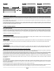
In addition, if the cable must cover a distance greater than 10 feet (3 m), a U-shaped loop must be used to minimize conductor thermal expan-
sion and prevent it from breaking (see FIG. 2, 3 and 4). Therefore, it is best to subdivide the area to be heated into runs of less than 10 feet. This
advice is valid for both types of installation. However, with cable spacers, you need to secure the cable runs and spacers with hot glue, placing
two spacer pieces back to back.
Buffer zone Buffer zone
Thermostat
sensor
Thermostat
Heating cable
Cable spacer
Heat sourceDrain
Min. 3 spaces
cable spacer
clearance
Wall or
fixed piece of furniture
FIG. 1