
Installation Guide


15
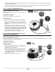
STEP 7: THERMOSTAT SENSOR
Based on the cable layout plan drawn up in the Planning and Design section, install the thermostat sensor between two heating cable runs, at
least 24 inches (60 cm) from the wall or centered between walls. Choose the location where the sensor wire does not cross over the heating cable
once it is passed through the base of the wall. Make sure you have enough cable to reach it to the thermostat junction box, and then use hot glue
to secure it to the oor. (see FIG. 16).
FIG. 16
STEP 8: PUT COLD CABLE IN THERMOSTAT JUNCTION BOX
Insert the cold cable (power lead) with the sensor wires into the conduit and the inside of the thermostat junction box, and leave 6 inches protrud-
ing. Secure excess cold wire to the oor (see FIG. 16) using hot glue. Make sure the cold cable on the oor does not protrude above the mem-
brane. Next, attach a metal plate to the base of the wall to protect the electrical wires in the groove.
STEP 9: INSTALL FLOOR COVERING ON MEMBRANE
Spread the thin-set with a notched trowel (1/4” x 3/8”) to cover the surface well and install the tiles on top, working in sections (learn more about
the procedure before getting started).
Grouting can begin no sooner than 24 hours after the installation has been completed. Use grout (with or without polymer-modied sand). Contact
the membrane manufacturer for information on selecting the appropriate thin-set and grout for your installation.
STEP 10: THIRD SERIES OF TESTS
Perform the three tests (see the Tests section). Record the results in the warranty booklet.
STEP 11: WIRING
Curing period
Initial start up of the oor heating system must be delayed until the end of the curing period (typically 28 days). Otherwise, the concrete’s+
adhesive properties will be compromised, thus reducing the oor covering adhesion. Contact a oor covering specialist to ensure proper system
start-up.
Wiring preparation
Make sure that the circuit turned off at the electrical panel.
The heating cable’s CSA identication tag must be in the junction box. Do not remove it from the cable.
The wiring of the cable to the thermostat or the relay must be made in accordance with the thermostat/relay manufacturer’s recommendations.
Connect the ground (green wire) at back of the junction box.
The heating cable must be connected to a thermostat with an integrated GFCI or GFCI-protected circuit installed in the electrical panel.
Identify the oor heating dedicated circuit using the label supplied with the warranty booklet (see FIG. 15).
Turn the power back on.
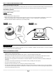
Metal plate
Thermostat
Splice
Cold cable
sensor
(power supply)
Conduit
Conduit
Splice
Metal plate
sensor
Thermostat
Cold cable
(power supply)