
Installation Guide


14
STEP 11: THIRD SERIES OF TESTS
Perform the three tests (see the Tests section). Record the results in the warranty booklet.
STEP 12: WIRING
Curing period
Initial start up of the oor heating system must be delayed until the end of the curing period (typically 28 days). Otherwise, the concrete’s adhesive
properties will be compromised, thus reducing the oor covering adhesion. Contact a oor covering specialist to ensure proper system start-up.
Wiring preparation
Make sure that the circuit turned off at the electrical panel.
The heating cable’s CSA identication tag must be in the junction box. Do not remove it from the cable.
The wiring of the cable to the thermostat or the relay must be made in accordance with the thermostat/relay manufacturer’s recommendations.
Connect the ground (green wire) at back of the junction box.
The heating cable must be connected to a thermostat with an integrated GFCI or
GFCI-protected circuit installed in the electrical panel.
Identify the oor heating dedicated circuit using the label supplied with the warranty
booklet (see FIG. 15).
Turn the power back on.
INSTALLATION WITH MEMBRANE
STEP 1: INSTALL MEMBRANE
Complete the oor preparation and membrane installation according to the manufacturer’s instructions. Wait until the mortar is dry (a minimum
of 24 hours).
STEP 2: PERFORM TESTS
Before breaking the plastic seal and unspooling the heating cable: Perform the three tests (see the Tests section). If all the results are compliant,
continue the installation. Record the results in the warranty booklet.
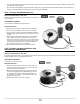
STEP 3: POSITION THERMOSTAT JUNCTION BOX
Install the thermostat junction box with the conduit, in accordance with the electrical codes effective in your area.
Cut a hole in the wall for a junction box at the desired location. At oor level, directly below the thermostat box, make a U-shaped groove in the
base of the wall (metal plate) to accommodate the entry of the power lead.
Determine the length of conduit needed between the inlet knockout of the junction box and the base of the wall (metal plate) according to the
electrical codes in your area.
Note: It is unnecessary to include an elbow at the base of the conduit, unless it is required by the electrical code in your area (see FIG 16).
STEP 4: SECURE SPLICE TO FLOOR
Position the splice on the oor (see FIG. 16) near the junction box (refer to your cable layout plan drawn up in the Planning and Design section). Cut
the membrane to a width of 2 spaces and the minimum length required to pass the cold cable through, and clean the excess cement below the splice.
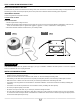
Dig a hole in the oor deep enough to hold the splice so that it is ush with the membrane. (Depth to dig: about ¼” to ½” or 6 to 13 mm). Clean
the oor, place the splice in the hole and secure it to the oor with hot glue. Make sure the cold cable lead installed on the oor does not protrude
above the membrane.
Then, attach a metal plate to the base of the wall to protect the electrical wires in the groove.
The splice must not be installed inside the wall.
STEP 5: RUN HEATING CABLE THROUGH MEMBRANE
Based on the cable layout plan drawn up in the Planning and Design section, run the heating cable through the membrane. When inserting the
cable into the membrane, make sure the heating cable is properly secured inside it. Remember to make a U-loop if the cable is longer than 10 feet
(see FIG. 4).
It is IMPORTANT to always maintain the same spacing between the cable runs on the surface to be heated, depending on the type of heating
desired (see Planning and Design section).
However, 2-space runs are acceptable in the buffer zone for only a few (2 to 3) cable runs. Since this tighter spacing will generate a higher
temperature, it should be used only where needed.
STEP 6: SECOND SERIES OF TESTS
Perform the three tests (see the Tests section). If all results are compliant, continue with the installation. Record the results in the warranty booklet.
Breaker No.
Product/ Produit
Voltage (VAC)
208/ 240
Amp (A)
4.7/ 5.4
Wattage/ Watt (W)
975/ 1300
Resistance/ Résistance
44.4 Ohms
No. Prod.
This breaker controls a floor heating
system / Ce disjoncteur protège un
système de plancher chauffant
CTXXXXXXXXXX
30-06-16-10-9
FIG. 15