
Installation Guide


12
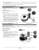
STEP 5: RUN HEATING CABLE THROUGH CABLE SPACERS
It is IMPORTANT to always maintain the same spacing between the cable runs on the surface to be heated, i.e. 3 spaces or 4 spaces, depending
on the type of heating desired (see Planning and Design section).
The heating cable must be tangent to the edge of the cable spacer; do not apply too much pressure on the cable (See FIG. 9) – 5 lbs max.
However, 2-space runs are acceptable in the buffer zone for only a few (2 to 3) cable runs. Since this tighter spacing will generate a higher tem-
perature, it should be used only where needed.
To maintain spacing between cable runs longer than 6 feet (1.8 m) and to prevent the cable from rising to the surface when self-leveling mortar is
installed, the use of hot glue is recommended to bond the termination joint as well as the center of each cable run (12” in length).
STEP 6: SECOND SERIES OF TESTS
Perform the three tests (see the Tests section). If all results are compliant, continue with the installation. Record the results in the warranty booklet.
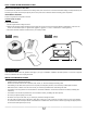
STEP 7: THERMOSTAT SENSOR
Install the thermostat sensor between two heating cable runs, at least 24 inches (60 cm) from the wall or centered between walls. Choose a location
where the sensor wire does not cross over the heating cable when it is passed through the base of the wall. Make sure you have enough cable to
reach the thermostat junction box, and then use hot glue to secure the cable to the oor. (see FIG. 11).
STEP 8: PUT COLD CABLE IN THERMOSTAT JUNCTION BOX
Make sure the circuit is not powered.
Insert the cold cable (power lead) with the sensor wires through the conduit into the inside of the thermostat junction box and leave 6 inches pro-
truding. Secure excess cold wire to the oor (see FIG. 11) using cable spacer pieces and hot glue. Make sure the cold cable installed on the oor
does not protrude above the plastic cable spacer. Next, attach a metal plate to the base of the wall to protect the electrical wires in the groove.
STEP 9: APPLY SELF-LEVELING MORTAR (SCRATCH COAT)
Using Tuck Tape-type adhesive tape, seal any area into which mortar may seep. Moreover, you must choose a waterproof r plywood (BC r).
Before buying another type of plywood, ask your cement manufacturer if it is suitable.
Once cable installation is complete and the primer has been applied (if required), you must cover the cables with either a polymer-modied
mortar meeting A1184 (A) ANSI standards or a self-leveling mortar (see CONCRETE SELECTOR TABLE to protect them and facilitate eventual
repairs. Mix the concrete in accordance with manufacturer instructions, and cover the heating cable with the concrete or mortar. The heating
cable must be completely covered by the concrete or mortar layer, making sure the thickness of the concrete is not exceed the manufacturer’s
recommendations.
Note: Although self-leveling mortar is by its very nature self-leveling, you may have to use a trowel to level the corners of the room. Wait
until the concrete or mortar is dry. Consult the manufacturer to nd out the required curing period.
The heating cable must always be embedded in concrete or covered by a thin concrete layer. Two methods are available: the SCRATCH COAT
(method recommended by STELPRO) and the THIN-SET METHOD (alternative method for experienced tile setters only). Please refer to the
CONCRETE SELECTOR TABLE below to nd out the type of concrete recommended for each method.
Splice
sensor
Metal plate
Conduit
Thermostat
Cold cable
(power supply)
FIG. 11
SCREW
STAPLE
FIG. 12