
Installation Guide


11
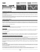
• To avoid damaging your heating cable, handle it carefully and use a wire feeder to unspool it (see FIG. 10).
• The tip of the hot glue gun must never touch the cable.
ELECTRICAL INSTALLATION REQUIREMENTS
The nominal maximum rated current of the branch circuit breaker or fuse supplying this product must be no greater than 20 A (15 A x 1.25).
Attach a label near the electrical panel to indicate the location of the installed heat units for easy identication.
INSTALLATION WITH CABLE SPACERS
STEP 1: PERFORM TESTS
Before breaking the plastic seal and unspooling the heating cable: Perform the three tests (see the Tests section). If all results are compliant,
continue with the installation. Record the results in the warranty booklet.
STEP 2: POSITION THERMOSTAT JUNCTION BOX
Using the cable layout plan drawn up in the Planning and Design section, install the thermostat junction box with the conduit, in accordance with
the electrical codes effective in your area.
Cut a hole in the wall for a junction box at the desired location. At oor level, directly below the thermostat box, make a U-shaped groove in the
base of the wall (metal plate) to accommodate the entry of the power lead.
Determine the length of conduit needed between the inlet knockout of the junction box and the base of the wall (metal plate) according to the
electrical codes in your area.
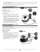
Note: It is unnecessary to include an elbow at the base of the conduit, unless it is required by the electrical code in your area (see FIG. 11).
STEP 3: SECURE SPLICE TO FLOOR
Position the splice on the oor (see FIG. 11) near the junction box (refer to your cable layout plan drawn up in the Planning and Design section).
Dig a hole in the oor deep enough to hold the splice so that it is ush with the heating cable. (Depth to dig: about 1/4” to 1/2” or 6 to 13 mm).
Clean the oor, place the splice in the hole and secure it to the oor with hot glue. Make sure the cold cable on the oor does not protrude above
the plastic cable spacer. Then, attach a metal plate to the base of wall to protect the electrical wires in the groove.
The splice must not be installed inside the wall.
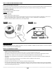
STEP 4: INSTALL CABLE SPACERS
Using the cable layout plan drawn up in the Planning and Design section, install the cable spacers at the planned locations and secure them to
the oor with No. 8 oor screws, or staples, or with hot glue (see Fig. 12). Leave a 3” clearance between the wall (or a xed piece of furniture)
and the cable spacer (see FIG. 1).
It is important to install the cable spacers so that the cable, once installed, lies perpendicular (90º) to them.
NORMAL TENSION
FIG. 9 FIG. 10
Cable spacer
tangent