
Installation Guide

10
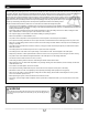
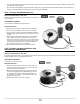
TEST 3: INSULATION RESISTANCE TEST
WHAT’S THE PURPOSE OF THIS TEST?
This test detects any break in the insulation of the heating cable, which could cause a current leak. Excessive leakage is usually detected by the
mandatory ground-fault circuit interrupter (GFCI) which cuts off power to the cable and renders the heating system inoperative.
INSTRUMENTS REQUIRED
A 1000-V megohmmeter is required for this test.
CAUTION: HIGH VOLTAGE
PERFORM THE TEST
1. Set the megohmmeter’s voltage to 1000 V.
2. Measure the insulation resistance between the grounding wire and one of the two power leads (BLACK or Red/Yellow). If the test is suc-
cessful, the result will be equal to or greater than 1 gigaohm (1 gigaohm = 1 G ohm = 1000 M ohms = 1000 megaohms).
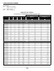
3. Record the insulation resistance measurement in your warranty booklet.
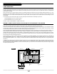
INSTALLATION
In the instructions below, follow the guidelines that apply to your type of installation: installation with cable spacers on a concrete or plywood
surface or installation with an uncoupling membrane.
INSTALLATION PRECAUTIONS
• Thoroughly clean the surfaces. These need to be strong, dry, clean and free of dust, oil, grease, paint, wax, protective coating, or any other
substance that may interfere with adhesion.
• Moreover, the surface must be free of all debris, nails, screws, etc. that could damage the heating cable.
• Avoid walking on the cables at the junction of the hot (white) and cold (black) sections, where the factory-installed splice is located.
• Make sure there is no debris on the sole of the shoes you wear during installation that could damage the cable.
• The suboor must comply with the recommendations for membrane installations. Consult the manufacturer for details (if installing with
membrane).
• The suboor must meet the requirements set out in the Suboor section (if installing with cable spacers).
• Do not drop or deposit anything on the cable.
• Be careful not to trip over the cable, as you could injure yourself and damage the cable.
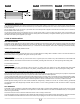
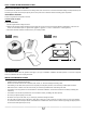
• Once the cable is inserted into the cable spacer, apply about 5 lb (2.3 kg / 22 N) of pressure on it before moving on to the next cable spa-
cer, and allow the cable to adopt its natural curve between the moulded hooks. Do not bend the cable at a right angle (90 degrees) where
it hooks into the cable spacers (see FIG. 9).
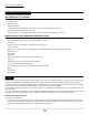
FIG. 7 FIG. 8
TEST 3 TEST 3
CONDUCTOR
BRAID OR
GREEN WIRE