INSTALLATION GUIDE SCU SERIES UNIVERSAL HEATING CABLE FOR INSTALLATION WITH MEMBRANES OR CABLE SPACERS This cable complies with CSA and UL standards For further information or to consult this guide online, please visit our website at www.stelpro.
TABLE OF CONTENTS WARNINGS 3 INSTALLATION 10 ELECTRICAL INSTALLATION REQUIREMENTS ...................................11 PRODUCT DESCRIPTION INSTALLATION WITH CABLE SPACERS................................................11 4 STEP 1: Perform tests ....................................................................11 TECHNICAL DESCRIPTION ..................................................................... 4 STEP 2: Position thermostat junction box ...................................
WARNINGS Before installing and operating this product, the user and the installer must read, understand and follow these instructions to avoid bodily harm or property damages, serious injuries and potentially fatal electric shocks. Keep them handy for future reference. If these instructions are not followed, the warranty will be considered null and void and the manufacturer will assume no further liability for this product.
PRODUCT DESCRIPTION °STELPRO universal heating cable is designed to heat a room with a heating cable placed under your floor covering. It can heat floor covering materials such as marble, ceramic and porcelain tiles, slate, granite as well as some poured surfaces. Before using this floor heating system under any other type of floor covering, contact your floor covering manufacturer to find out whether it’s appropriate for this type of installation.
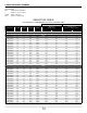
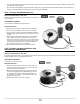
CODING AND MODEL NUMBERS The description of the alphanumeric product coding used in this installation guide is as follows: SCU1W0203S19 SCU : °STELPRO universal cable 1: Voltage 1 = 120 V, 2= 240 V W0203 : Power = 203 Watt S019 : Surface = 19 square feet SELECTION TABLE ACCORDING TO THE MEMBRANE OR CABLE SPACERS USED PRODUCTS VOLTAGE AMPERAGE LENGTH POWER MEMBRANE CABLE SPACER* Spacing: 3 Density: 12 W/ft2 Spacing: 3 or 4 Density: 3 = 12 W/ft2 4 = 9 W/FT2 3 spaces = 3.63” (92 mm) 3 spaces = 3.
PLANNING AND DESIGN CABLE SELECTION Before getting started, consider what the heating goal is for the room. Do you want to heat the entire room or simply keep your feet warm? The answer to this question will determine the spacing between cable runs; a 3-space runs will heat a room without the need for a secondary source of heating (baseboard or convector), while 4-space runs will keep feet warm but, for greater comfort, the system will need to be combined with another source of heating.
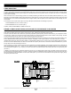
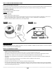
FIG. 2 FIG. 3 U-LOOP WITH CABLE SPACERS FIG. 4 U-LOOP WITH MEMBRANE 10 ft (3 m) THERMOSTAT SELECTION Only a thermostat equipped with a floor sensor maximizes the floor heating system’s efficiency and, therefore, your comfort. All other control methods (e.g. ambient air thermostat or switch) are not recommended since they cannot control the floor temperature. As a result, the floor temperature will always be either too cold or too warm.
Surface and subfloor preparation Refer to the membrane manufacturer.
• Once the cable is installed, but before it is covered with concrete or mortar. If the tests indicate that the cable is defective, the electrician is responsible for fixing the problem. • Once the cable is fully installed, covered and the floor covering is dry. If the tests indicate that the cable is defective, the contractor is responsible for fixing the problem (i.e. replacing the cable and redoing the installation). TEST 1: CONDUCTOR RESISTANCE TEST WHAT’S THE PURPOSE OF THIS TEST? FIG.
TEST 3: INSULATION RESISTANCE TEST WHAT’S THE PURPOSE OF THIS TEST? This test detects any break in the insulation of the heating cable, which could cause a current leak. Excessive leakage is usually detected by the mandatory ground-fault circuit interrupter (GFCI) which cuts off power to the cable and renders the heating system inoperative. INSTRUMENTS REQUIRED A 1000-V megohmmeter is required for this test. CAUTION: HIGH VOLTAGE PERFORM THE TEST 1. Set the megohmmeter’s voltage to 1000 V. 2.
• To avoid damaging your heating cable, handle it carefully and use a wire feeder to unspool it (see FIG. 10). • The tip of the hot glue gun must never touch the cable. FIG. 9 NORMAL TENSION FIG. 10 Cable spacer tangent ELECTRICAL INSTALLATION REQUIREMENTS The nominal maximum rated current of the branch circuit breaker or fuse supplying this product must be no greater than 20 A (15 A x 1.25).
FIG. 11 FIG. 12 Cold cable (power supply) Conduit STAPLE SCREW Splice Metal plate Thermostat sensor STEP 5: RUN HEATING CABLE THROUGH CABLE SPACERS It is IMPORTANT to always maintain the same spacing between the cable runs on the surface to be heated, i.e. 3 spaces or 4 spaces, depending on the type of heating desired (see Planning and Design section). The heating cable must be tangent to the edge of the cable spacer; do not apply too much pressure on the cable (See FIG. 9) – 5 lbs max.
CONCRETE SELECTOR TABLE* CABLE EMBEDDING (SCRATCH COAT ONLY) USAGE SPECIFIC CONCRETE PRODUCTS CERAMIC TILE ADHESIVE GROUT STANDARDS Self-leveling mortar YES NO NO N/A** Polymer-modified mortar*** YES YES NO ANSI A118.4 (A) Polymer-modified grout (with or without sand) NO NO YES ANSI A118.6 (A) or A118.7 (A) Epoxy grout NO NO YES ANSI A118.
STEP 11: THIRD SERIES OF TESTS Perform the three tests (see the Tests section). Record the results in the warranty booklet. STEP 12: WIRING Curing period Initial start up of the floor heating system must be delayed until the end of the curing period (typically 28 days). Otherwise, the concrete’s adhesive properties will be compromised, thus reducing the floor covering adhesion. Contact a floor covering specialist to ensure proper system start-up.
STEP 7: THERMOSTAT SENSOR Based on the cable layout plan drawn up in the Planning and Design section, install the thermostat sensor between two heating cable runs, at least 24 inches (60 cm) from the wall or centered between walls. Choose the location where the sensor wire does not cross over the heating cable once it is passed through the base of the wall. Make sure you have enough cable to reach it to the thermostat junction box, and then use hot glue to secure it to the floor. (see FIG. 16). FIG.
ABOUT THE WARRANTY ATTENTION! The warranty booklet must be COMPLETED and RETURNED to °STELPRO to activate the warranty. Failing which THE WARRANTY WILL NOT BE ACTIVATED AND WILL NOT BE VALID. ALL REQUIRED INFORMATION AND TEST RESULTS MUST BE ENTERED IN THE BOOKLET, ACCORDING TO THE INSTRUCTIONS IN THIS GUIDE. Please also fill out the warranty card on our website: www.stelpro.com/en-CA/warranty. WARRANTY This limited warranty is offered by °STELPRO Design Inc.