
Owner's Manual

6
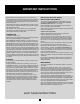
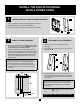
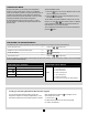
L1
L2/N
GND
F F
A
D
E
C
B
G
G
MOTOR
ELECTRONIC
THERMOSTAT*
THERMAL
PROTECTIONS
ELEMENT
ELEMENT
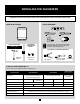
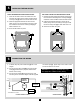
1. If needed, strip the power cable wires [A] with a wire
stripper.
2. Connect the grounding wire [B] rmly with the green
screw [C] provided for this purpose, located at the
bottom of the housing.
3. Connect the fan heater [D] and power supply wires
according to the connection diagram with the supplied
connection caps [E]. Tighten caps on the wires to make
sure the connections are secure.
6
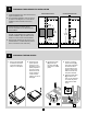
CONNECTING THE WIRING
CONNECTION DIAGRAM
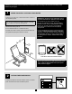
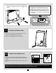
FOR A RECESSED FAN HEATER INSTALLATION
1. Insert the fan heater into the hole made in the wall
and mark the position of the screws according to the
mounting holes [F]. Make sure the fan heater is level.
2. Install the appropriate brackets to secure the fan
heater (4.3 kg or 9.4 lb) according to the type of wall.
Use at least two of the three mounting holes [F] on
either side of the unit.
3. Screw the fan heater into place.
FOR A WALL MOUNT FAN HEATER INSTALLATION
1. Place the fan heater against the wall and mark the posi-
tion of the screws according to the mounting holes [G]
at the back of the unit. Make sure the fan heater is level.
2. Install the appropriate brackets to secure the fan
heater (4.3 kg or 9.4 lb) according to the type of wall.
Use all mounting holes [G] on either side of the unit.
3. Screw the fan heater into place.
ELECTRICAL DIAGRAM OF THE DEVICE
5
INSTALLING THE FAN HEATER
WARNING: Use copper or aluminium wires only.
Use supply wires suitable for 90 °C (194 °F).
*Models WITH thermostat ONLY