
Use and Care Manual


3
INSSORB1017
Cut off power supply at circuit breaker or fuse before proceeding to the installation. Use the appropriate screw sets (minimum head
diameter 1/4 in (6.5 mm)) and anchors according to the wall type and the weight of the product (10 lbs). When drilling into the wall,
make sure not to damage the electrical wiring and other hidden utilities.
N.B. This product must be connected by a certied electrician, according to the electrical and building codes effective in your region.
This unit is designed for permanent installation and can be installed two ways.
WARNING – High temperatures may be generated under certain abnormal conditions. Do not partially or fully cover or obstruct the
front of this heater.
INSTALLATION
WARNING!
NEVER POSITION TOWELS OR ANY
OTHER TEXTILE FABRICS IN SUCH A WAY
THAT THEY PARTIALLY OR COMPLETELY
OBSTRUCT THE PRODUCT. SUCH AN
OBSTRUCTION WILL CAUSE THE UNIT
TO OVERHEAT.
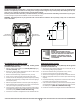
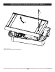
RECESSED DEVICE INSTALLATION
RECOMMENDED HEIGHT: 10 in (254 mm) off the ground
(certied at minimum 6 in)
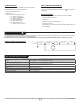
1. Make an opening in the wall which is 14 1⁄8 in (359 mm) high by
10 1⁄2 in (267 mm) wide.
2. Remove the screw located underneath the unit and take off the
front cover by pulling it gently upwards.
3. Remove the electrical wiring compartment cover (1 screw).
4. Punch out one of the knock outs and insert the power cable.
5. Insert the unit into the wall opening and secure it in place by screwing
at least two (2) of the three (3) mounting holes on the outer edging of
the unit (min 4 points)
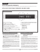
6. Make the appropriate electrical connections (see wiring diagram).
7. Put the electrical wiring compartment cover back on and screw the
unit in place using the previously removed screw.
8. If this unit will be controlled by a wall-mounted thermostat (without
an integrated thermostat), use the switch above the motor to select
the desired power (1000 W or 2000 W model only).
9. Put the front cover back on and tighten the screw underneath the unit.
SURFACE INSTALLATION
RECOMMENDED HEIGHT: 10 in (254 mm) off the ground
(certied at minimum 6 in)
1. Remove the screw located underneath the unit and take off the
front cover by pulling it gently upwards.
2. Remove the electrical wiring compartment cover (1 screw).
3. Punch out one of the knock outs and insert cables.
4. Secure the unit using the four (4) holes located on the back of the unit.
5. Make the appropriate electrical connections (see electrical wiring
diagram).
6. Put the electrical wiring compartment cover back on and screw the
unit in place using the previously removed screw.
7. If this unit will be controlled by a wall-mounted thermostat (without
an integrated thermostat), use the switch above the motor to select
the desired power (1000 W or 2000 W model only).
8. Put the front cover back on and tighten the screw underneath the unit.
14
1/8"
359 mm
10 1/2"
267 mm
SURFACE
INSTALLATION
RECESSED
INSTALLATION
RECESSED
INSTALLATION