USER’S GUIDE SORB SERIES HIGH-END FAN HEATER TÈME QUAL ITÉ SYS For further information or to consult this guide online, please visit our website at www.stelpro.
WARNING IMPORTANT INSTRUCTIONS Before installing and using this product, you must read and understand these instructions and keep them for future reference. If the installer and the user do not follow these instructions, the manufacturer cannot be held liable in any way and the warranty will be null and void. This product must be installed by a qualified person and connected by a certified electrician, according to the electrical and building codes effective in your region. For indoor installation only.
INSTALLATION Cut off power supply at circuit breaker or fuse before proceeding to the installation. Use the appropriate screw sets (minimum head diameter 1/4 in (6.5 mm)) and anchors according to the wall type and the weight of the product (10 lbs). When drilling into the wall, make sure not to damage the electrical wiring and other hidden utilities. N.B. This product must be connected by a certified electrician, according to the electrical and building codes effective in your region.
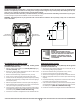
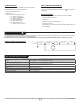
OPERATION WITH A WALL-MOUNTED THERMOSTAT Choose a thermostat equipped with a TRIAC, which makes it possible to maintain a precise temperature, thus increasing your level of comfort. WITH A BUILT-IN ELECTRONIC THERMOSTAT FOR SMART HOMES DISPLAYED ITEM LISTING 2 1 Zigbee connectivity status ( 2 The 3 1 4 6 10 7 ). 8 9 5 11 8 Ambient room temperature (or the temperature setpoint, if the display is flashing). In BOOST mode, the BOOST mode time remaining. icon if the unit is overheating.
BUTTON FONCTIONS BUTTONS MAIN SCREEN ADVANCED MENUS UP BUTTON OR DOWN BUTTON Set the temperature setpoint* Browse and edit settings BOOST BUTTON Activate/deactivate BOOST mode Select and confirm BOOST setting (in the BOOST menu) UP AND DOWN BUTTONS SIMULTANEOUSLY FOR 3 SECONDS Access advanced menus Exit advanced menus BOOST BUTTON FOR 3 SECONDS Access BOOST menu Exit BOOST menu UP AND DOWN BUTTONS SIMULTANEOUSLY FOR LESS THAN 3 SECONDS --- Selection in Advanced Menus *If the UP or DOWN but
°STELPRO MENU UNIT OVERHEAT DETECTION Information about the unit is available in the advanced menus. This unit can detect when it is overheating. Follow these steps to access this information: If your unit’s thermal protection gets activated, an the display. -- Access the advanced menus. -- Select menu 7. icon will flash on FACTORY RESET -- Select one of the following sub-menus: • 7.1: Version of convector • 7.2: Version of Zigbee Radio • 7.3: Day manufactured • 7.4: Month manufactured • 7.
TROUBLESHOOTING PROBLEM DEFECTIVE PART OR PART TO CHECK The unit does not work The unit runs continuously The housing is extremely hot The desired room temperature cannot be reached Overheating The heater is on and the breaker trips The unit does not heat Thermal protection is activated, which translates to ventilation without heat. In the built-in electronic thermostat version, an alarm is also displayed. The connectivity icon ( ) flashes on the screen.
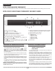
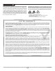
REPLACEMENT COMPONENTS LIST RÉF. # PART # DESCRIPTION 1 ELF-043 ELEMENT WITH INTEGRATED PROTECTION 2 MO-086 240 V MOTOR/FAN 3 P-SORB00D0 HOUSING 4 KIT-SORB01 FRONT COVER 5 ST-291 THERMOSTAT (SORB2002W MODEL) CIR-051 THERMOSTAT POWER SUPPLY (SORB2002W MODEL) SWI-051 SWITCH (SORB2002WCW MODEL) 6 7 M-SORB11ZW2 SLEEVE 8 S-050/10/QT/MS FACADE SCREWS: MECANICAL SCREW, BUTTON HEAD, QUADREX, 1/2 in, 10-24 7 5 3 2 6 OR 1 4 8 STELPRO DESIGN INC.
MAINTENANCE N.B.: In order for the warranty to remain valid, the unit’s air intake and output vents and interior must be cleaned on a regular basis. N.B. High voltage and the risk of electric shock are present in the unit even if the thermostat is set to off. Therefore, you can receive an electrical shock as long as the unit is under power.
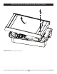
INSTRUCTIONS TO REMOVE THE FRONT PANEL 1 2 1. Remove the screw. 2. Remove the front panel by pulling and pushing it up.